09 Sep 2026 - Compression, No Spark
09 Sep 2026 - Compression, No Spark
Back out with the starter refitted, a battery on it, and a compression tester. The plan was the one written at the end of the 07 September visit. Crank it with no spark to clear the bores, then compression-check it, then try for a start.
Short version. It cranks, it has compression on all four, and it will not fire. The ignition coil ohms out open on the secondary.
Cranking it and clearing the bores
Compression test went well. I was happy to see the engine start.
The engine turns over on the starter, plugs out, in long pulls. The clip above runs about forty seconds and covers three of them, the first about ten seconds and two shorter ones after it.
On “start”, to save the next reader the double-take
The engine did not fire on this visit. There was no spark all day, which the rest of this page covers. “Start” here means it started turning, on the starter. The clip bears that out, three separate bursts of cranking with silence in between rather than anything running on its own.
It spat a lot of stuff out of those cylinders, and it kept doing it. It eventually cleared up mostly and was just smoking out a little bit. I’m wondering whether there’s water in the top end. Coolant level isn’t low.
What was coming out, and why the coolant level matters
Some of it is the two weeks of penetrant. The 07 September visit finished with Kroil pouring back out of the plug holes as the crank turned, and the plugs went back in on top of it. Anything left in the bores gets blown straight out on the first starter pulls, and it burns off as smoke once the bores warm up from the cranking.
A full coolant level argues against a head gasket, but it does not settle it. Water in the top end has two easy routes here that have nothing to do with a gasket. Four plug holes stood open to the rain for a long time (22 August, 23 August), and a gallon or more of water came out of the crankcase on 23 August, so anything standing in the block can still work its way up. A gasket leak that fills a bore usually takes coolant level down with it, and it hasn’t.
The cheap way to separate those causes is a compression test done twice. That is what the readings below are, and the same gauge answers the head gasket question. The manual’s test is specific. Two adjacent cylinders low, and adding oil to them not helping, points at the gasket surface between them. Scattered readings, or low ones that come up with oil, do not.
Compression
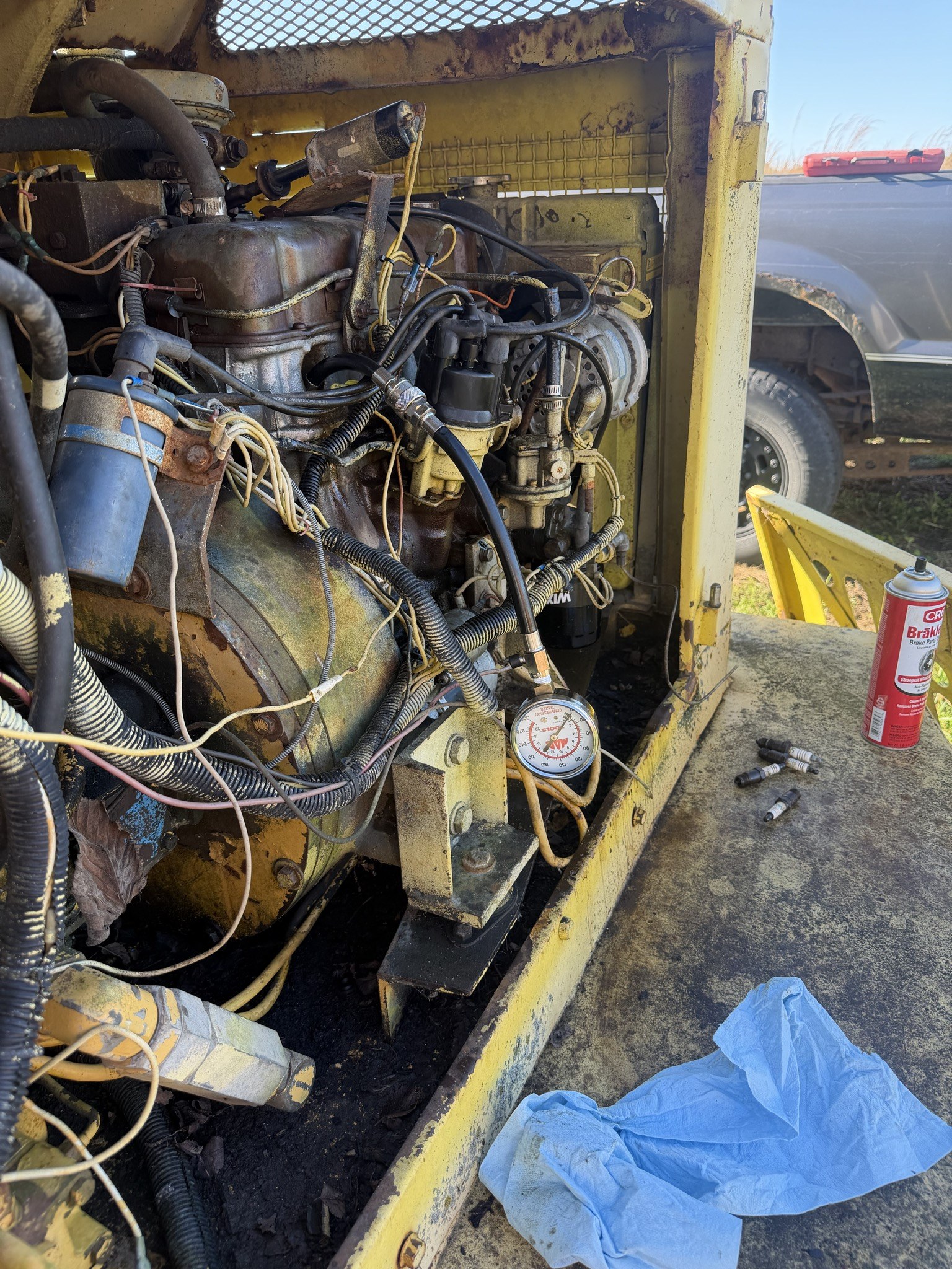
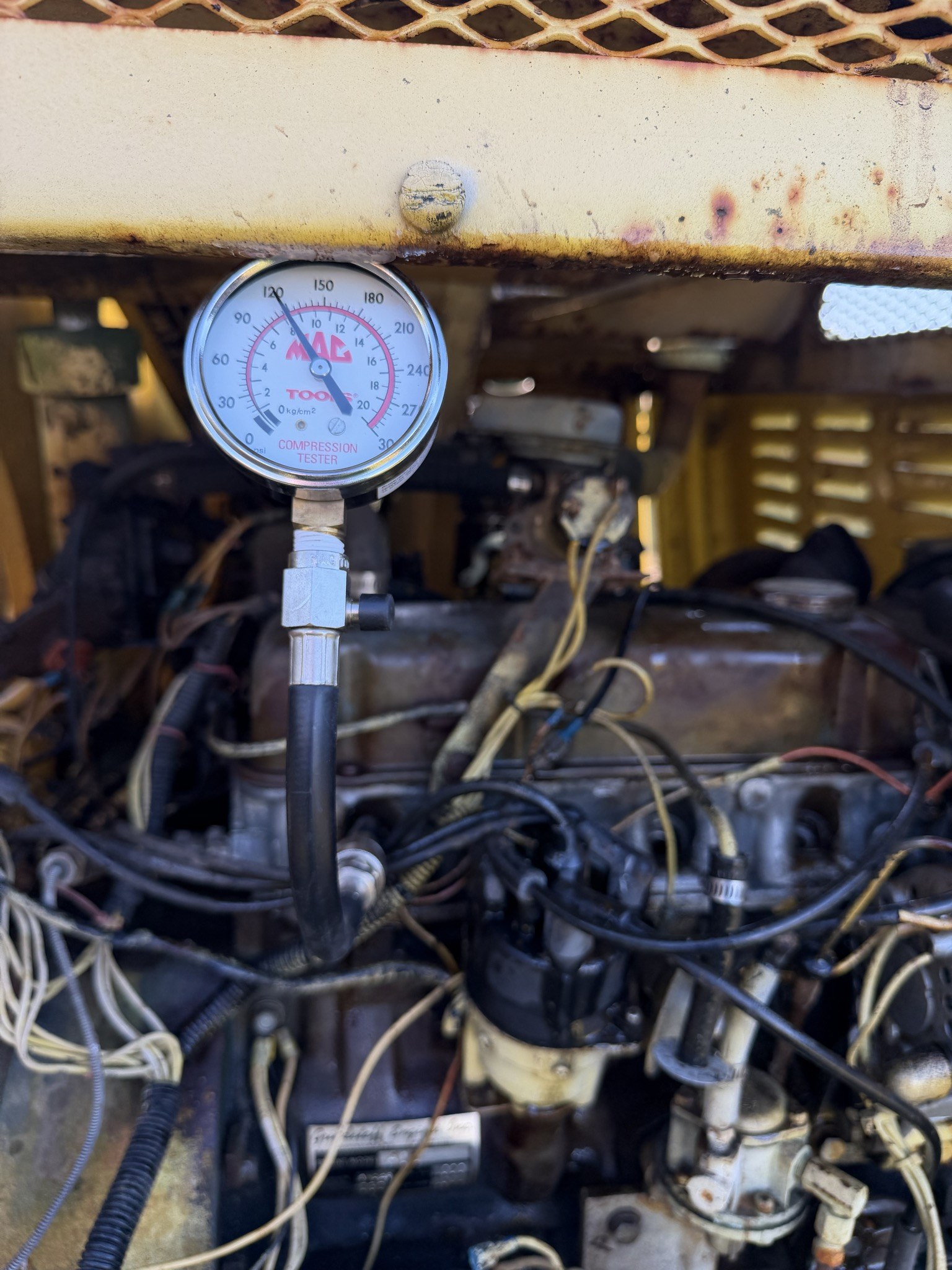
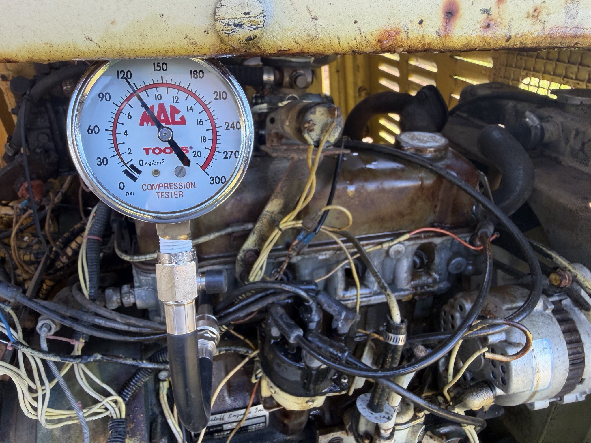
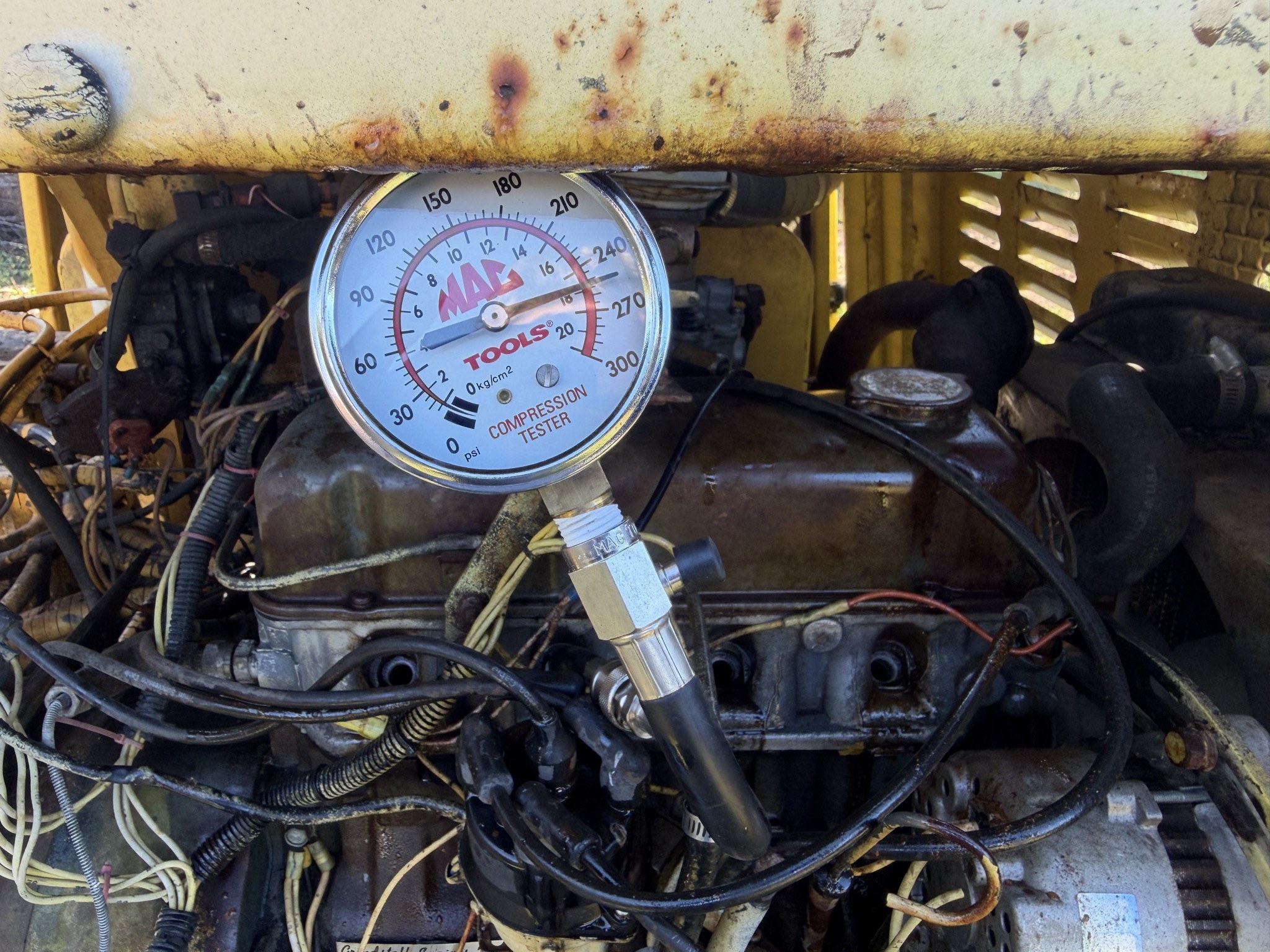
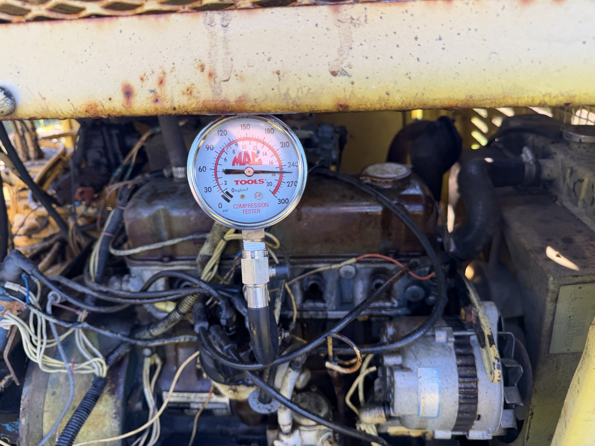
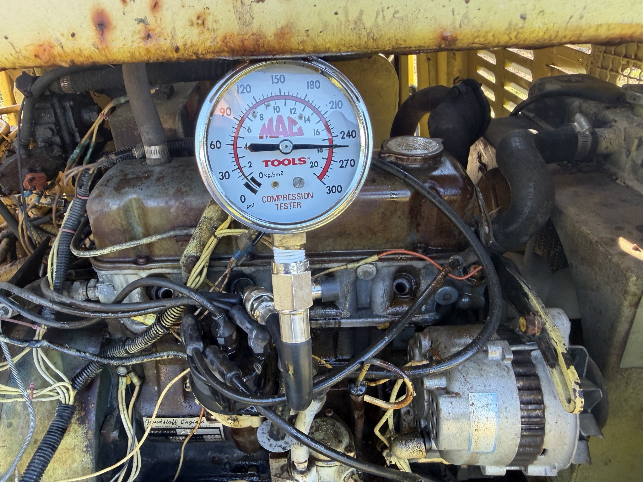
I ran through it a few times because the readings were all over the place. I’m guessing stuck valves, something like that, but I am getting compression across all cylinders, so that’s good news.
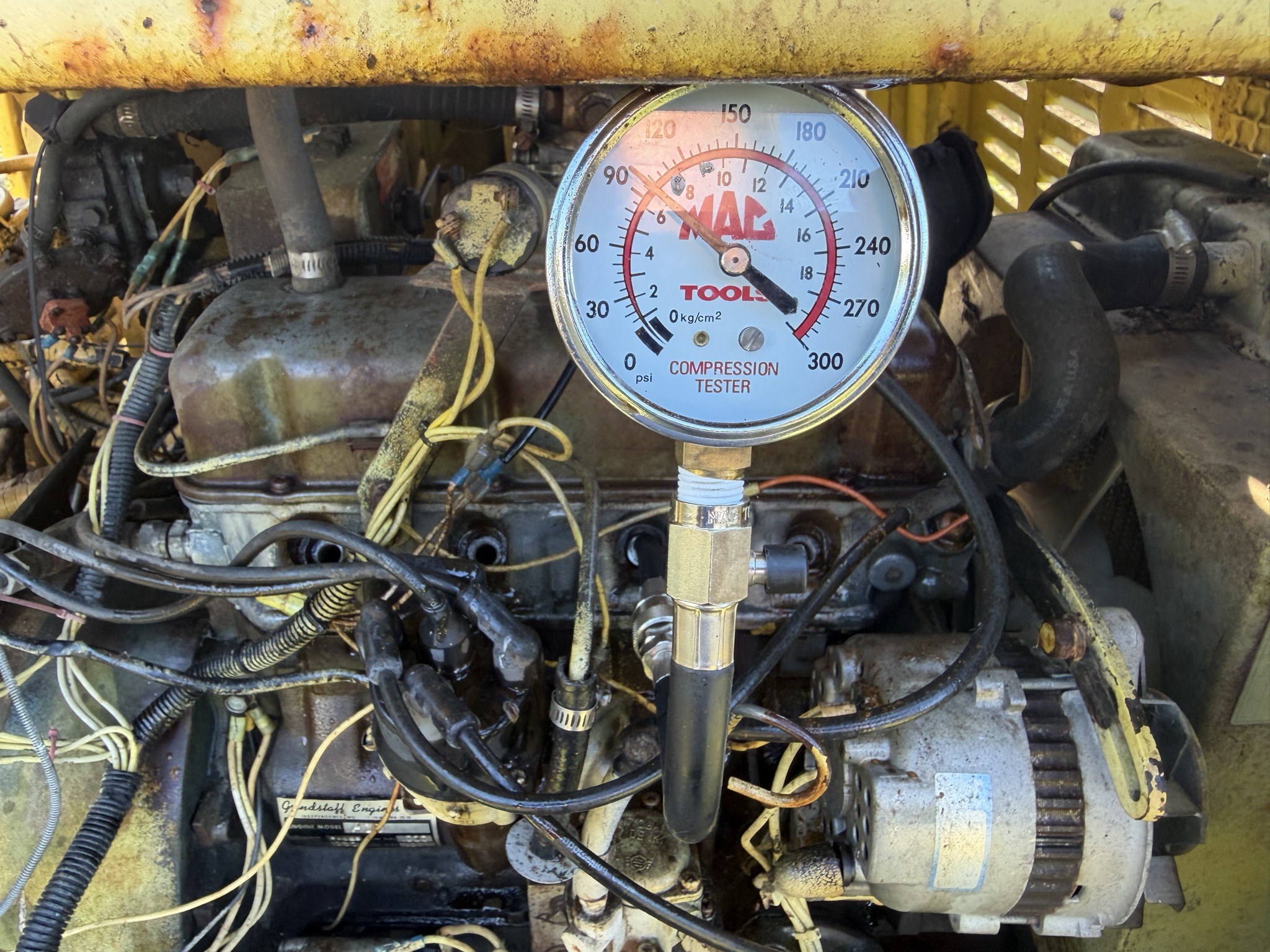
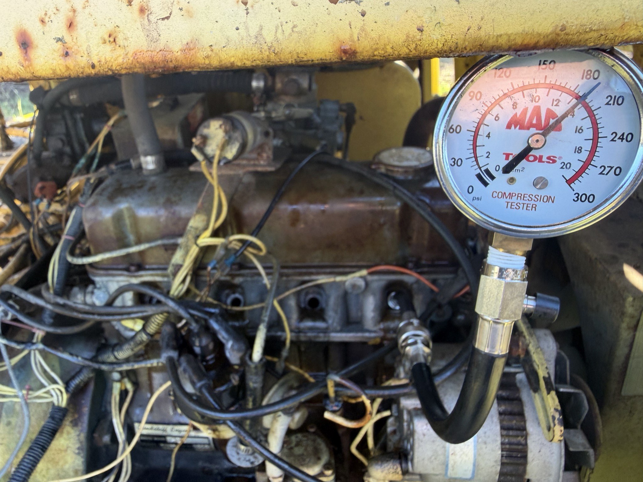
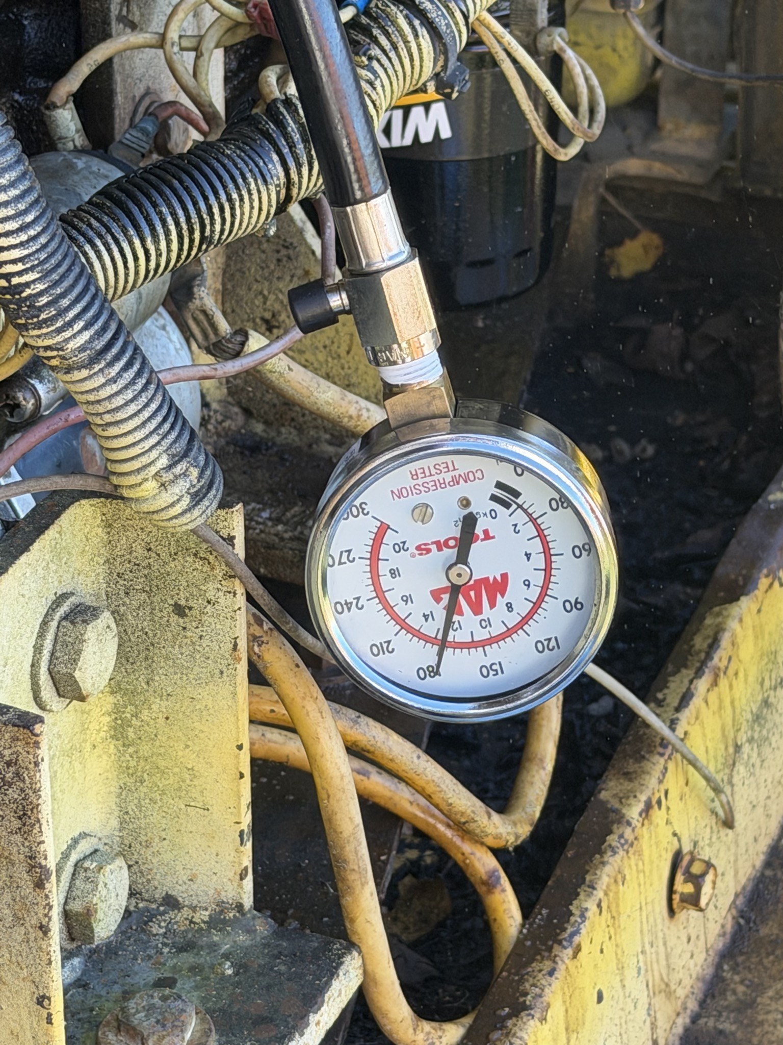
What the gauge faces say, and what the factory numbers are
These are dial readings taken off the photographs, not numbers written down at the machine. Read in the order the photos were taken, the pointer sits at roughly 120, 120, 250, 250, 250, 90 and 185 psi. Call it plus or minus 10 psi, because reading a dial off a photograph at these angles is not better than that. An eighth photo shows the tester lying on the frame rail after it came off, still holding 180, which is almost certainly the last of those seven read a second time rather than an eighth measurement. If you wrote numbers down at the machine, yours supersede all of these.
How the needle was read, since it is easy to get backwards. This gauge has one rigid needle with a long pointer on one side and a short blunt counterweight on the other, 180° apart. The pointer reaches out to the printed psi numerals; the counterweight stops well short, inside the scale ring. The photo of the tester lying on the rail settles which is which, because there the short arm sits in the blank gap between “300” and “0” where no pointer can ever go. Read the short arm by mistake and a 250 becomes a 60.
Nothing in the photos records which cylinder any reading belongs to, or which of the several passes it came from, so this is a spread rather than a per-cylinder result. Writing the number next to the cylinder number on the next pass is the fix, and it costs nothing.
The factory numbers, for comparison. The Nissan engine service manual service data page gives compression pressure as 1,245 kPa (12.7 kg/cm², 181 psi) at 350 rpm standard, with a minimum of 981 kPa (10.0 kg/cm², 142 psi) at the same cranking speed. That is now on Specs.
The three 250 psi readings cannot be compression
They are above what this engine can physically make. At roughly 9:1 compression, cranking against atmosphere, the theoretical ceiling is somewhere near 240 psi and a healthy real engine lands well under it, which is why the factory figure is 181. A gauge reading 250 on a cranking A15 is not reporting a strong cylinder. It is reporting that something in that cylinder is not a gas.
The most likely cause is liquid in the bore, which is exactly what was going on. Liquid does not compress. Any that is left sitting on the piston crown eats the clearance volume and sends the indicated pressure far above normal. The 07 September visit ended with Kroil pouring out of the plug holes and the plugs going back in on top of it, and the note above this one records the engine spitting material out and only gradually clearing. Three impossible readings and a bore full of penetrant are the same fact seen twice.
The other candidate is the gauge itself. A compression tester holds its peak until the release valve is pressed. Three consecutive readings landing within a few psi of each other, at a value the engine cannot produce, is also what a gauge looks like when it was not bled between cylinders. That is worth ruling out on the next pass by watching the needle return to zero before each reading.
What the credible readings actually say
Setting the three impossible ones aside, what is left is 185, 180, 120, 120 and 90 psi.
- The 185 and 180 are at the factory standard of 181. At least one cylinder, tested twice, makes full factory compression on a cold engine turning on a tired battery. Nothing in this engine is worn out
- 120 psi is below the 142 psi service minimum but is a normal figure for a bore that is still carboned, rusted or damp, on an engine that had not turned at all until two days earlier
- 90 psi is the one to chase, and it is exactly what the wet-versus-dry test below is for
Cranking speed is a caveat on every low number here. The factory figure assumes 350 rpm with the throttle held wide open. A tired battery, a cold reman starter and a partly closed throttle all read low, and none of them mean anything is wrong. Worth confirming the throttle is being held open on the next pass.
The manual’s own next step separates rings from valves
The service manual gives the test for exactly the question above. Where a cylinder reads low, pour a small amount of engine oil into that cylinder through the plug hole and repeat the test.
- If adding oil raises the reading, the piston rings are worn or damaged
- If the reading stays low, a valve is sticking or not seating
- If two adjacent cylinders read low and adding oil does not help either of them, there is leakage past the head gasket surface
That is a wet-versus-dry test and it takes about five minutes with tools already in the box. It turns “I’m guessing stuck valves” into an answer. Given this engine’s history, a third possibility sits alongside the first two, which is a ring simply stuck in its groove with rust and carbon rather than worn, and that one can free up with running time and does not need the head off.
One line from the same page is worth having in front of you. Right after the head gasket branch, the manual notes that oil and water in the combustion chambers can result from that problem. On an engine that stood full of water and has just been ejecting liquid, that sentence cuts both ways, and it is another reason to get the bores dry before trusting any number.
The distributor finally has a number on it
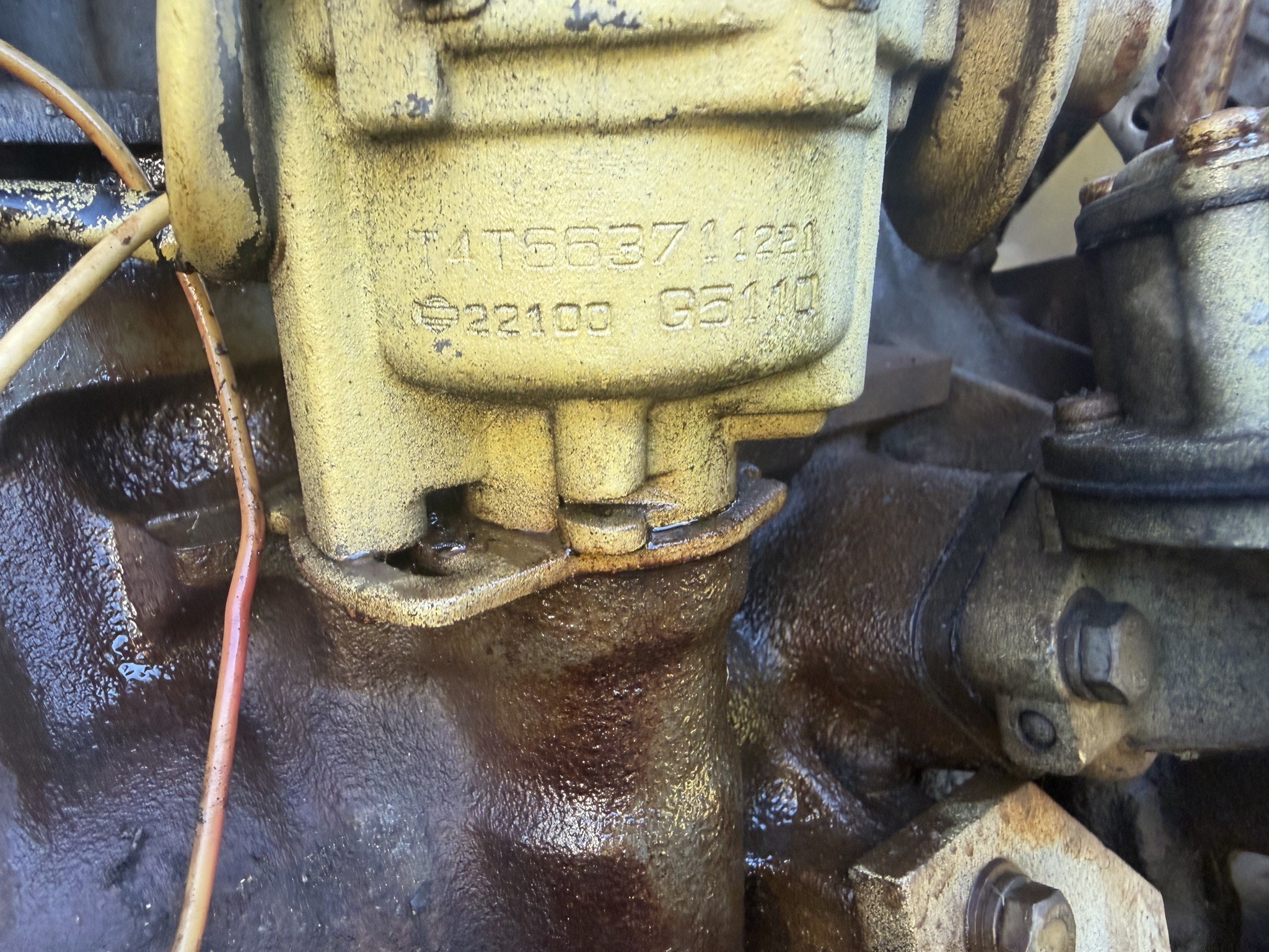
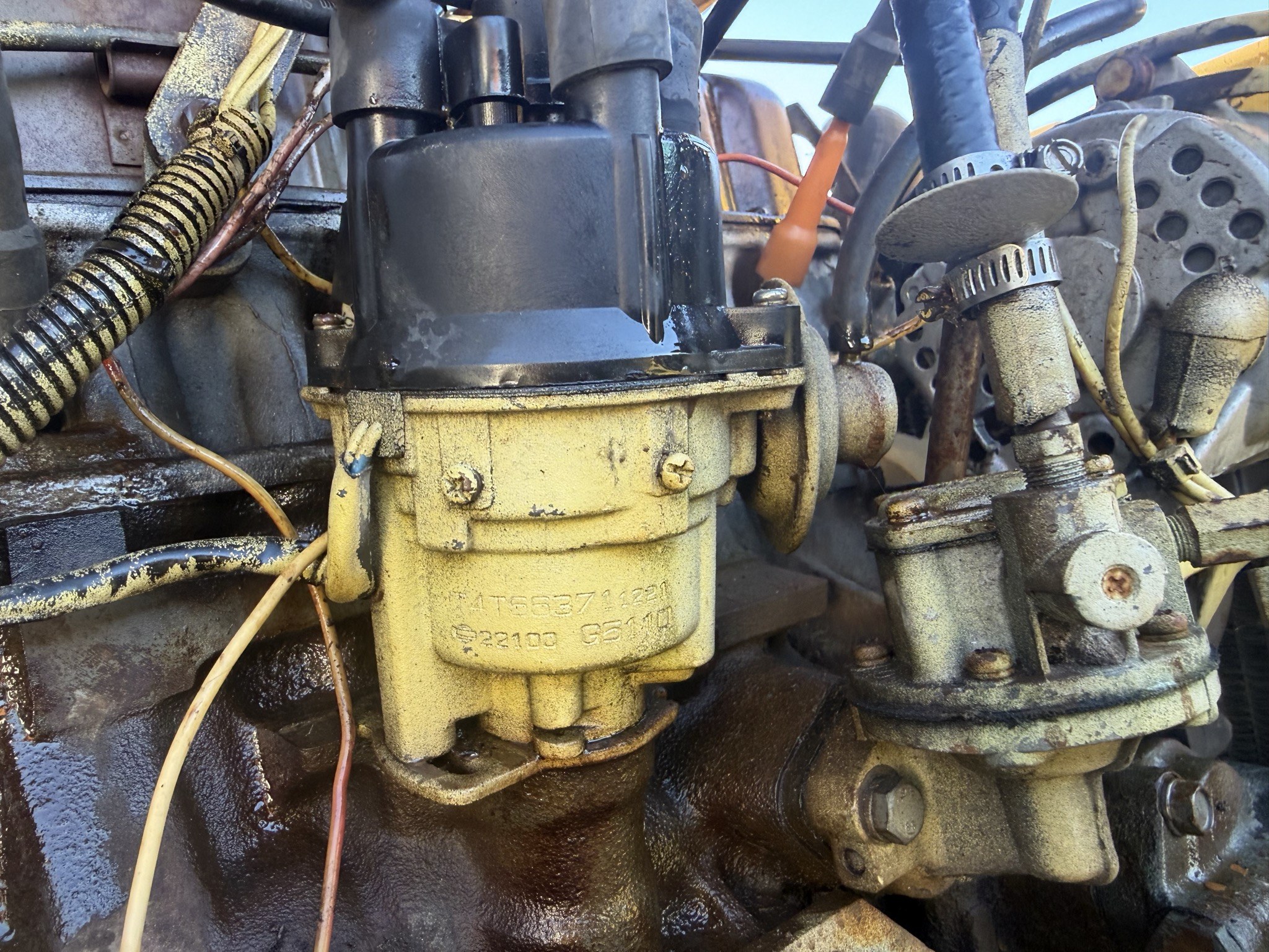
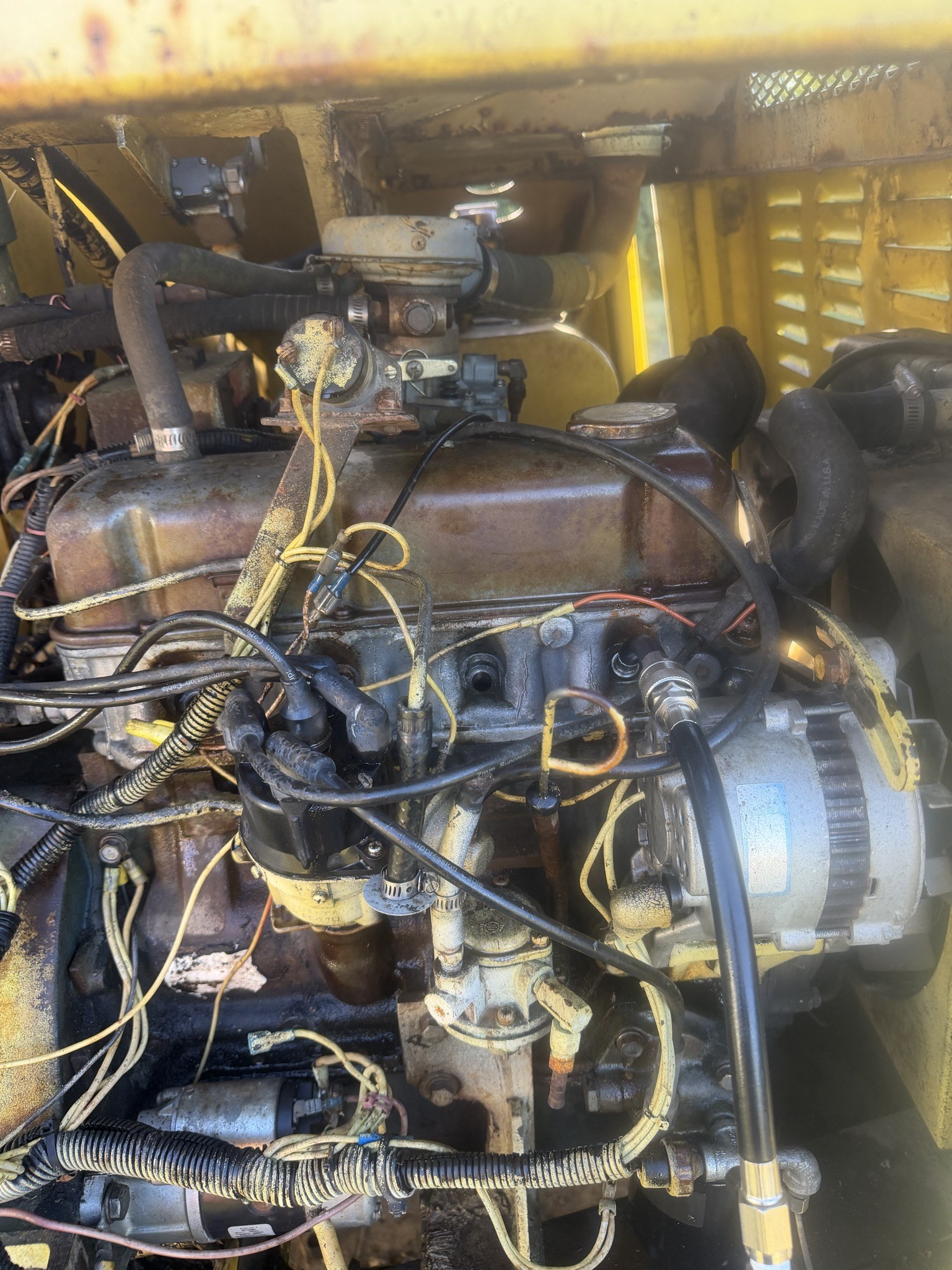
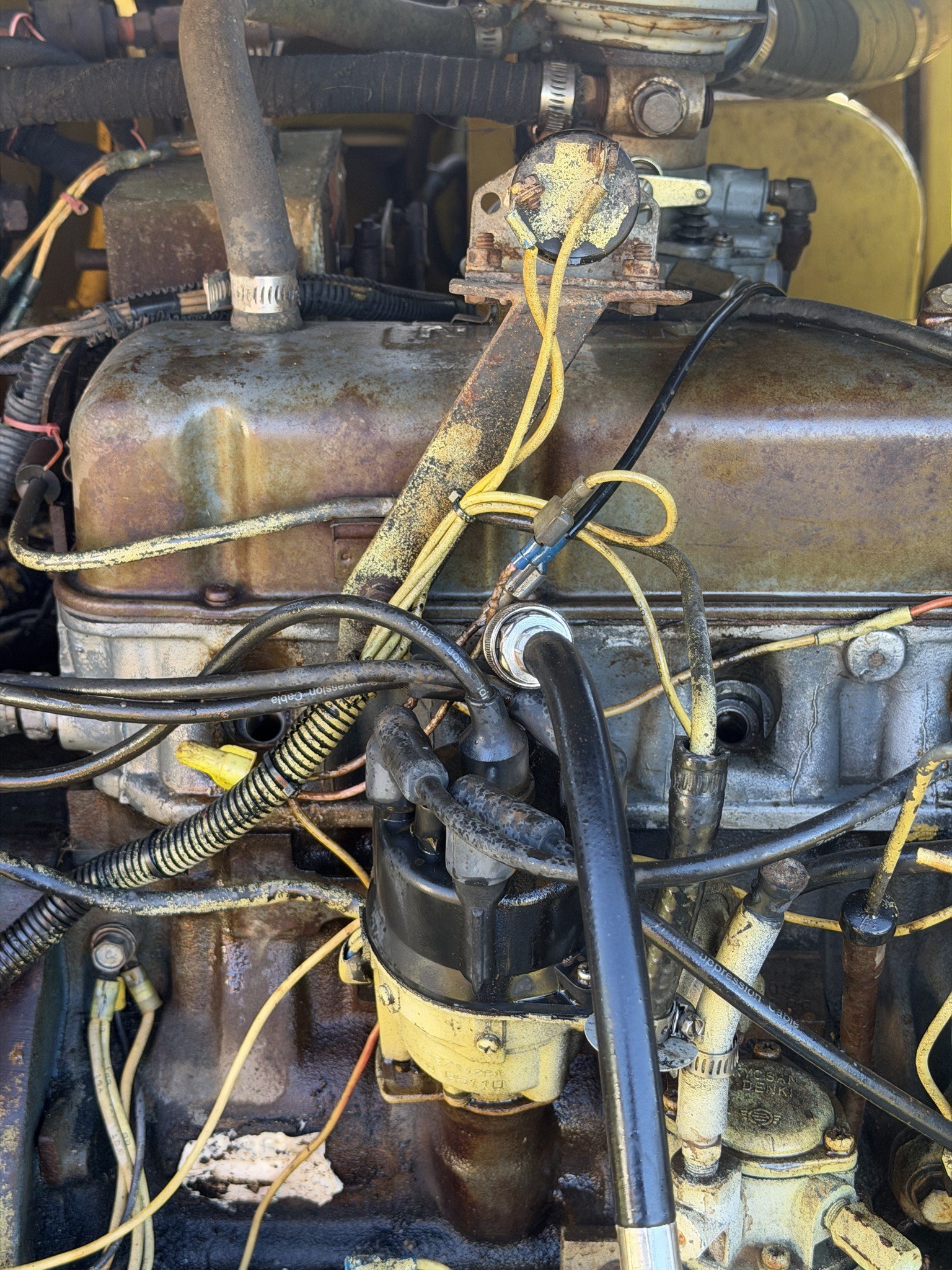
I found that the number one cylinder is the one facing towards the back, so as you’re looking at the engine, that one right in the middle facing towards you is number one, going counterclockwise, 1-3-4-2.
I didn’t see a separate capacitor in that distributor, but I’ll have to check the manuals and make sure there isn’t one there. There shouldn’t be, since it is electronic.
This closes a gap that has been open since the first visit
No distributor number had ever been read off this machine. Nothing in 22 August, which photographed the distributor with its cap off, in 23 August, in 07 September, or in the original walk-round notes carries one. The casting on the body carries two, stamped straight into the aluminium.
- T4T56371, followed by 1221, on the upper line. The first is the Mitsubishi Electric unit number; the trailing group is a date or lot code and is the only thing in the set that could date the distributor
- 22100-G5110 on the lower line, next to the maker’s mark, which is the Nissan part number
Both are stamped into a rough casting and neither is crisp. The G in the Nissan suffix is a solid read. The 5 and 6 in the middle of the Mitsubishi number are the soft ones, and that pair is exactly the kind of digit OCR and eyes both get wrong. Put a light on the casting and confirm both before ordering against either.
It corroborates the electronic-distributor finding independently. The engine service manual documents this engine’s distributor as Mitsubishi T3T03581, a breaker-point unit, and publishes point gap and dwell figures for it (service data page, p.EL-19). That table has an A12 column and an A15 column, and the T3T03671 in the other column is the A12’s distributor, not a second option for this engine. The unit actually fitted is a T4T number, a different and later family. That agrees with what Grove’s own engine harness drawing said all along, which is “ELECTRONIC DISTRIBUTOR” (parts catalog pp.152-154, harness assembly 6512002038), and with the physical inspection on 22 August that found no points inside. Three independent sources now. Firing Order records the question as settled.
On the missing capacitor, that is the correct observation. A condenser exists to stop mechanical breaker points burning themselves out. There are no points in this unit, so there is nothing for a condenser to protect and none is fitted. The service manual’s exploded distributor view does show a condenser, but that view is of the T3T points unit, which is not what is on this engine. Some electronic units carry a small external noise-suppression capacitor on the housing, which is not the same part and is not required for the engine to run.
The No. 1 cap tower is identified, by Method A. Thumb over the No. 1 plug hole, crank until compression pushes it off, carry on to TDC, pull the cap and read where the rotor is pointing. That is the Firing Order step 1 procedure done properly, and it is the one to trust, because it establishes the tower from the engine itself rather than from any assumption about how the distributor is clocked.
The result is that No. 1 is the tower facing the rear of the vehicle. From there the leads walk counterclockwise 1-3-4-2, which matches the factory table for both the order and the rotation direction. How the engine sits in the machine is recorded on the 13 September page.
This is now recorded on Firing Order, so the walk does not have to be redone from scratch next time the cap comes off.
No spark, and the coil is open
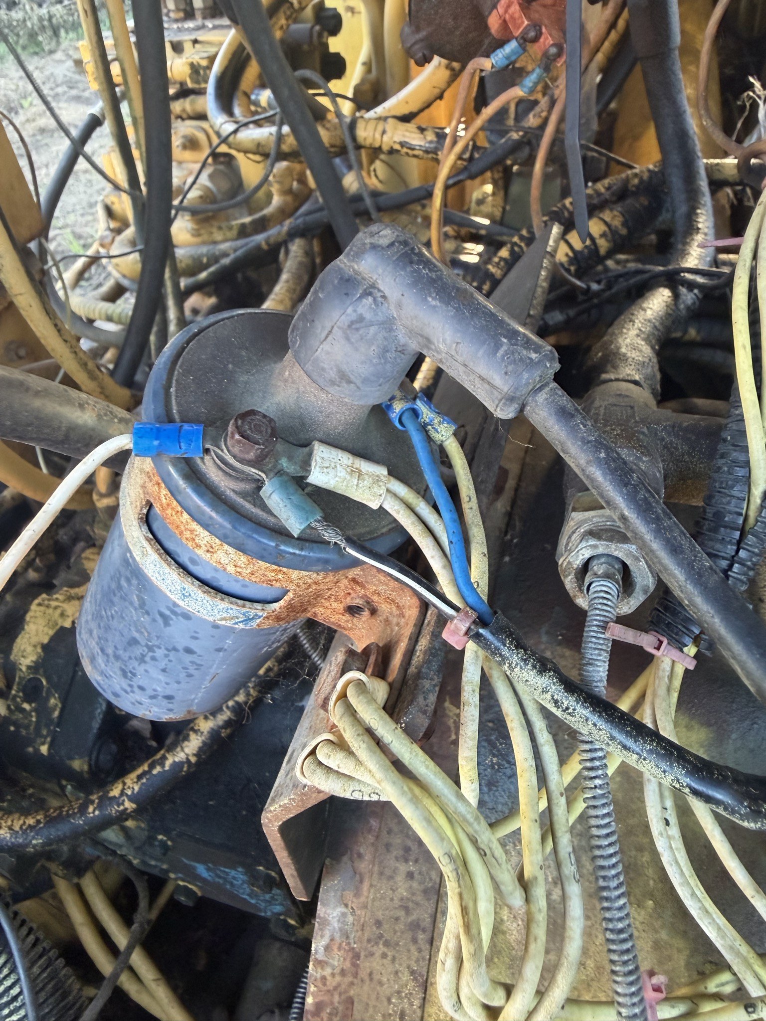
I wanted to throw my spark tester on one of the plugs and I got no spark. So I checked with my clamp-on multimeter tester at the coil, and no spark there either.
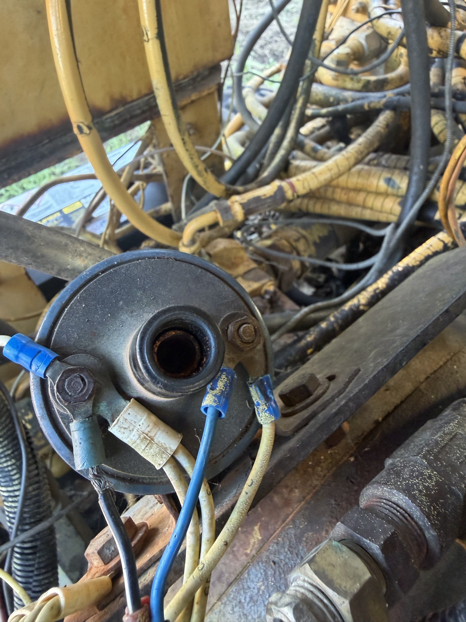
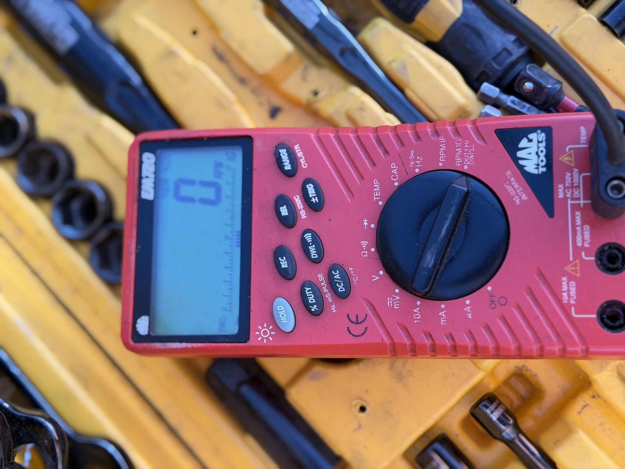
So I ohmed out the primary and secondary windings, and it looks like the coil is bad.
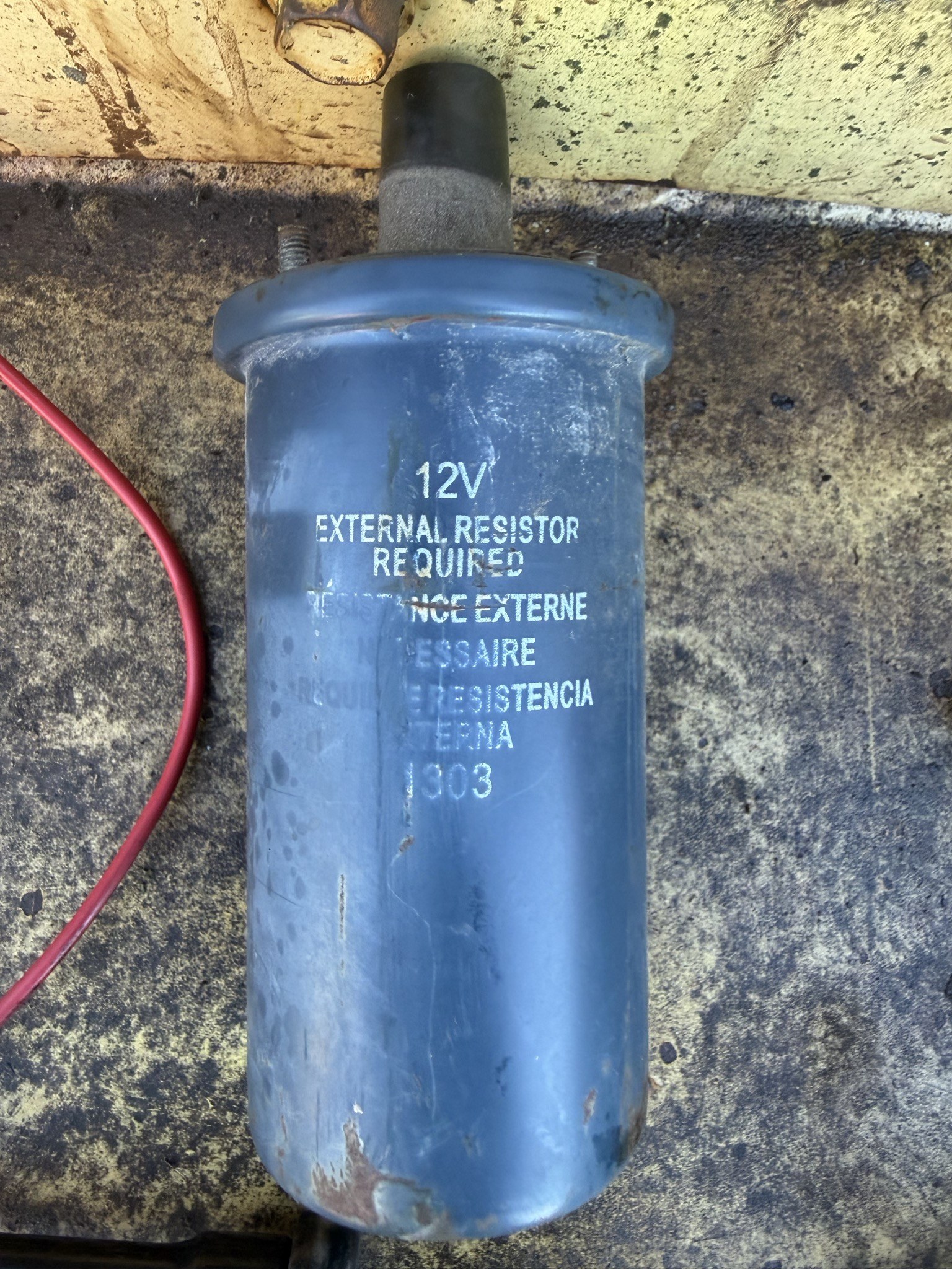
The coil is dead, and the label on it is a finding in its own right
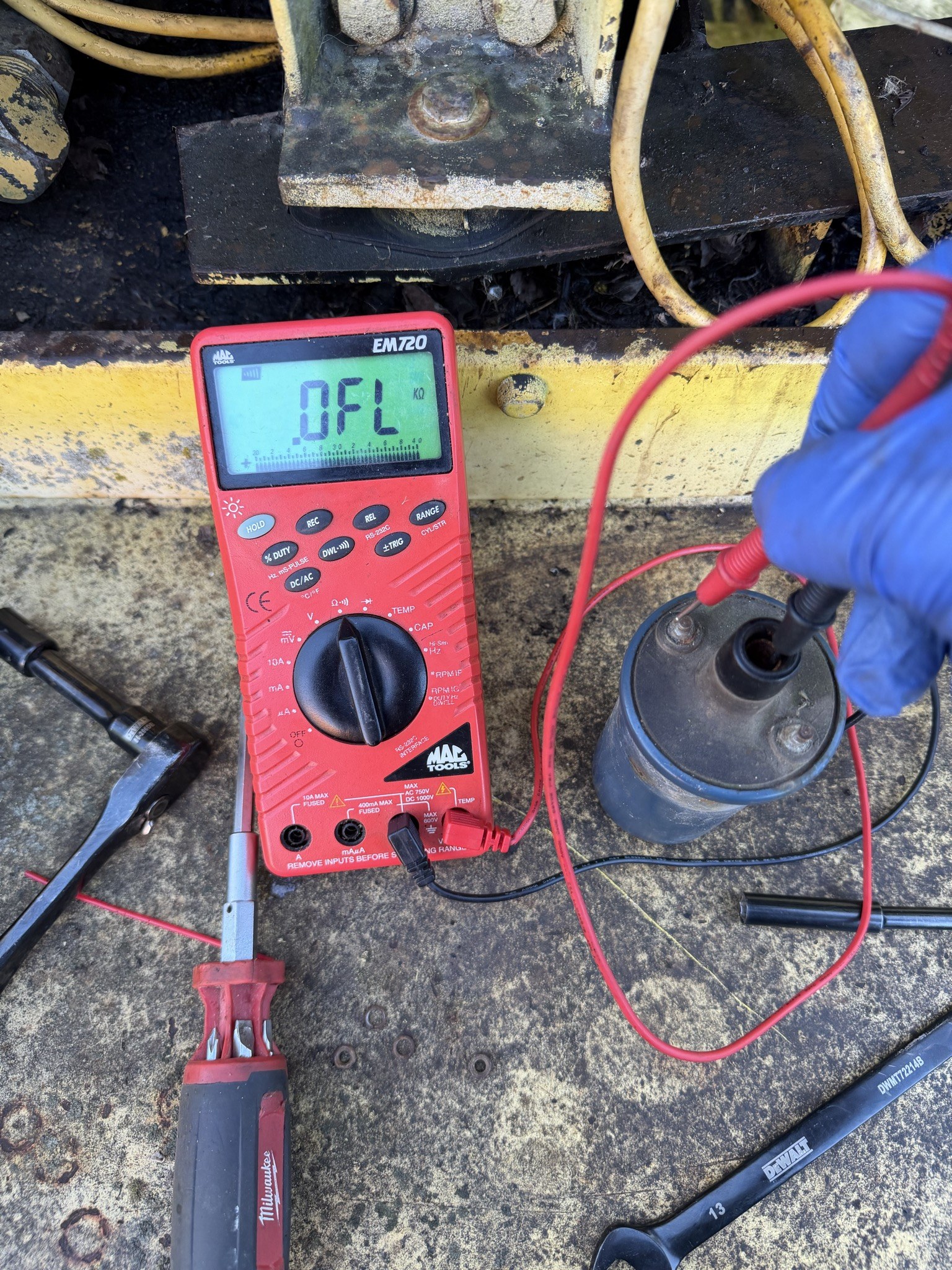
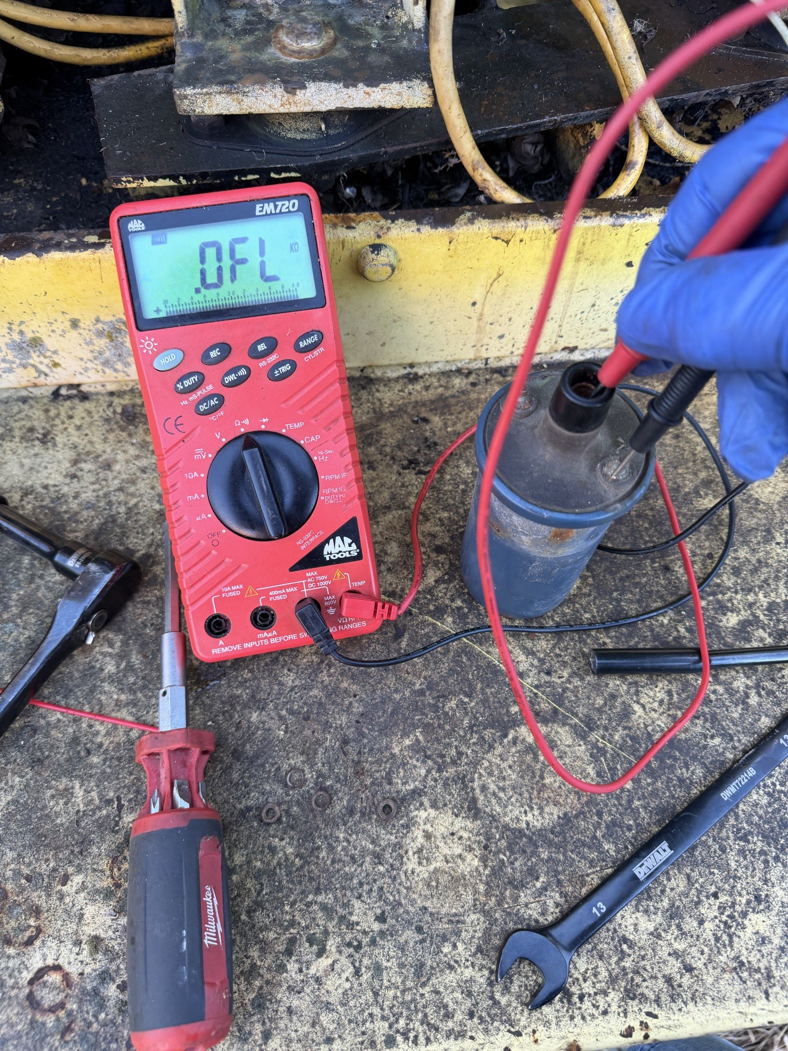
The secondary is open circuit. Probe in the high-tension tower and probe on either low-tension terminal both give OFL on the meter, the EM720’s over-limit display, which is an open rather than a high reading. A healthy coil secondary is a few thousand ohms. An open secondary cannot produce a spark under any condition, no matter what the rest of the circuit is doing. That is a complete and sufficient explanation for the no-spark condition, and it matches the spark tester and the clamp-on both showing nothing.
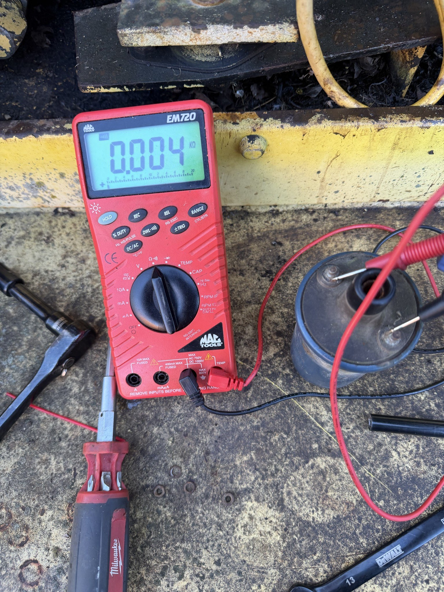
The primary reads about 4 ohms, and the factory figure is 1.5. The meter shows 0.004 kΩ across the two low-tension terminals. The engine service manual specifies this coil’s primary resistance as 1.5 Ω ±10% at 20 °C, so 1.35 to 1.65 Ω (p.EL-19). Four ohms is about 2.4 times spec. Both windings are out of spec, not just the secondary. There is nothing left to argue about with this coil.
The factory coil is a Mitsubishi HP5-13E10 (→ now SMP UC12), named on p.GI-2 of the engine service manual and again on p.EL-19. It is a ballast-type coil, which is why the one on the machine is stamped “12V EXTERNAL RESISTOR REQUIRED”, and why its published primary resistance is the 1.5 Ω quoted above. The coil fitted is the correct type. It has simply died.
This engine is supposed to have that resistor, and it is worth finding before fitting a new coil. The engine service manual ignition system description says it plainly. The circuit is equipped with a resistor, and during cranking the current bypasses the resistor so the coil sees full battery voltage and the starting spark stays strong. So the right replacement is another external-resistor coil, and the resistor and its cranking bypass both need to be found and checked. Fitting an internally-resisted coil in place of this one, and leaving the original resistor in circuit, gives a weak spark that gets worse as the engine warms up. Nothing labelled as an ignition ballast resistor appears in Grove’s engine harness drawing (parts catalog pp.152-154, harness assembly 6512002038, three sheets), which does label the ignition coil, an ignition relay, the electronic distributor and the anti-diesel and choke solenoids, so the resistor is most likely on the Nissan side of the harness, either as a block near the coil or as a resistance wire.
Do check the feed before assuming the coil is the only fault. A dead coil masks everything downstream of it. The owner’s own next-visit list already has “check the 12 V power coming into the coil” on it, which is the right instinct, and the note below on the kill switch is a second reason to do it.
The switch on the lower panel
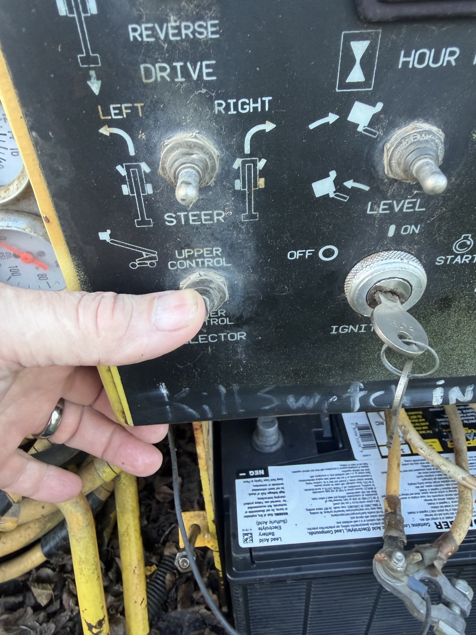
There’s a switch on the lower control panel that says it needs to be pressed. I’m not sure whether that needs to be pressed to actually start the engine. I tried it both ways. It cranks with just the key, and I don’t know whether that press-and-hold switch is just for the controls or whether it’s for the ignition as well.
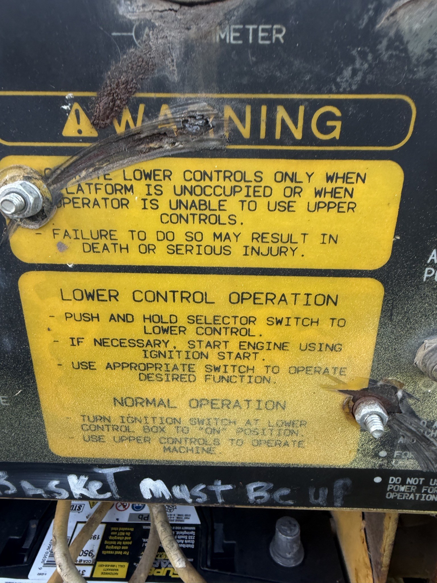
The machine’s own placard answers this
The decal photographed right next to the switch spells the sequence out. It opens with a warning that belongs here in full, because it is the same rule Startup is built around.
Warning
“Operate lower controls only when platform is unoccupied or when operator is unable to use upper controls. Failure to do so may result in death or serious injury.”
Lower control operation
- Push and hold selector switch to lower control
- If necessary, start engine using ignition start
- Use appropriate switch to operate desired function
Normal operation
- Turn ignition switch at lower control box to “ON” position
- Use upper controls to operate machine
So the selector switch routes control power, and the engine is started on the key. The operator’s handbook describes the same switch as the two-position PLATFORM CONTROLS / GROUND CONTROLS rotary selector on the lower left of the ground controls, spring returned up to PLATFORM CONTROLS, and says that in that position it “controls all electrical power to the platform controls and removes all power from ground control functions.” It routes function power between the two control stations. It is not in series with the engine’s ignition. The placard’s own wording puts starting the engine after holding the selector, and qualifies it with “if necessary”, which only makes sense if the engine can already be running or can be started separately.
Being straight about what this does and does not settle. The handbook passage describes what the selector does in one position and says nothing directly about the ignition circuit, so “it is not in series with the ignition” is a reading of the documents rather than something they state. The observation that it cranks on the key alone cannot settle it either, because with an open coil there is no spark whichever way the switch is held, so that test had no power to discriminate.
The handbook does say one thing that points the right way. The ignition switch “must be in the ON position to supply electrical power to the platform controls”, which puts the ignition upstream of the control stations rather than downstream of the selector.
And the switch on this machine is not quite the one the handbook draws. The photo shows a toggle labelled UPPER CONTROL / LOWER CONTROL SELECTOR. The handbook describes a two-position rotary. Same function by the placard’s account, but treat the match as an inference.
So measure it next time, since the meter will already be out. Key on, check for 12 V at the coil feed terminal, with and without the selector held. Thirty seconds, and it turns a reading of two documents into a fact.
And the marker writing is a kill switch
The two shots above catch adjoining stretches of the same line somebody wrote in marker along the bottom edge of the ground control panel. Together they read “Kill switch in … basket must be up”.
This identifies the switch the 22 August note could not
The 22 August visit photographed “Switch in basket must be up” and left it open, and it has been sitting on the task list since as an unidentified switch. The word “kill” is legible in this visit’s photo, which is the part that was missing.
The operator’s handbook documents exactly one switch that fits. The EMERGENCY STOP switch on the bottom left of the platform controls, in the basket. Pushing it in removes all electrical power from the controls and stops the engine, and the handbook’s instruction is to pull it out again before resuming starting operation. A previous owner writing “kill switch in basket must be up” is telling the next person to pull that mushroom head out.
The handbook makes this a live item for the no-spark condition, not just a curiosity. Its own warning about ground-controls diagnostics reads “WHEN TESTING FUNCTIONS AND MONITORING THE RELAY BOARD IN THE GROUND CONTROLS, THE EMERGENCY STOP SWITCH IN THE PLATFORM CONTROLS MUST BE PULLED OUT AND THE KEY-OPERATED IGNITION SWITCH IN THE GROUND CONTROLS MUST BE” on. That is this exact situation, spelled out. The starting procedure says the same thing in miniature, “Pull out EMERGENCY STOP switch” immediately before starting. This does not displace the open coil secondary, which is measured twice and sufficient on its own, but it is exactly the kind of second fault that hides behind a first one. Check it is pulled out before spending time chasing a feed that reads dead.
It has not been physically verified on this machine yet. The identification is from the handbook plus the marker writing, not from putting hands on the switch. That is the confirming step.
The Import Direct parts went back in the box
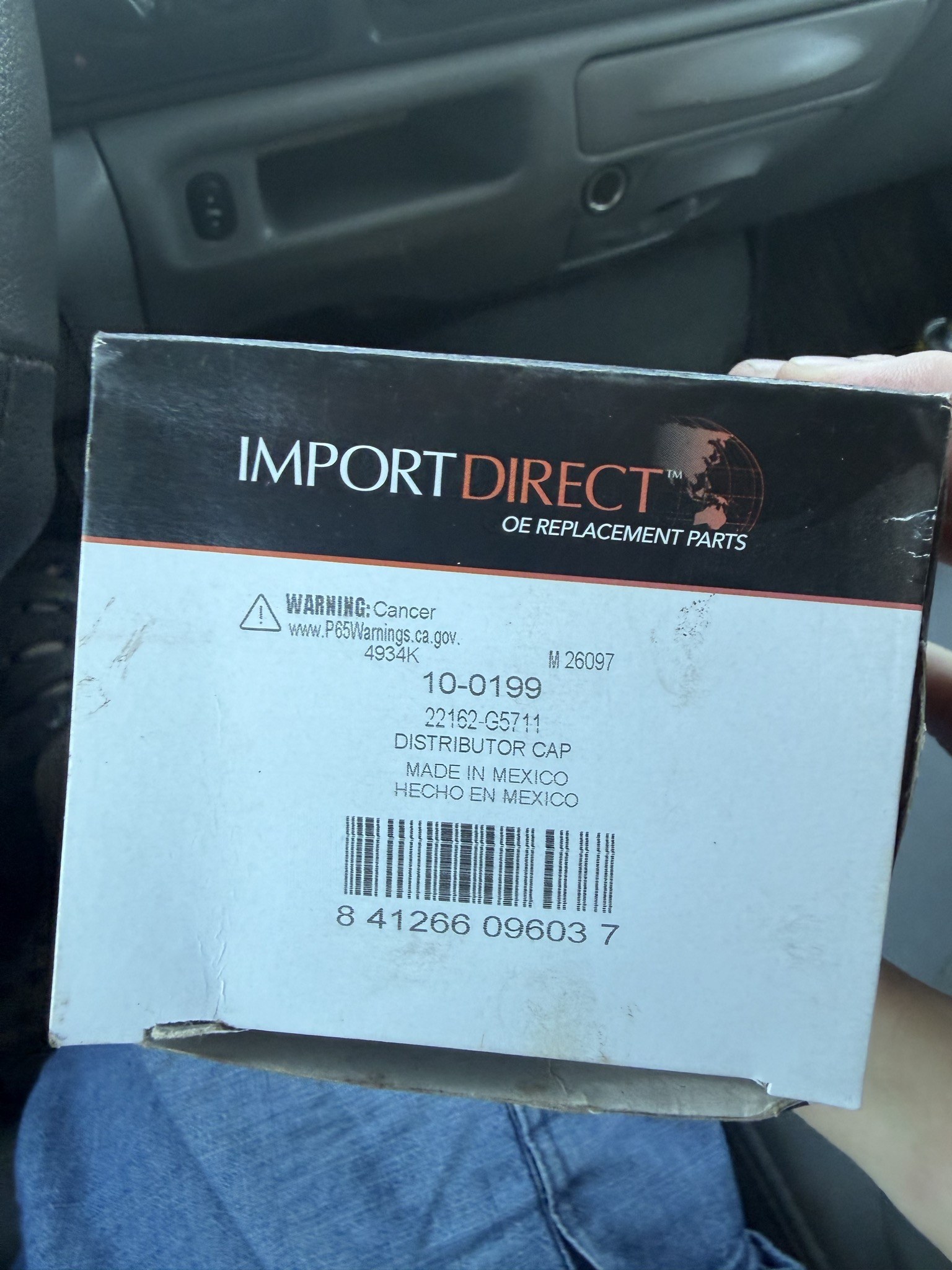
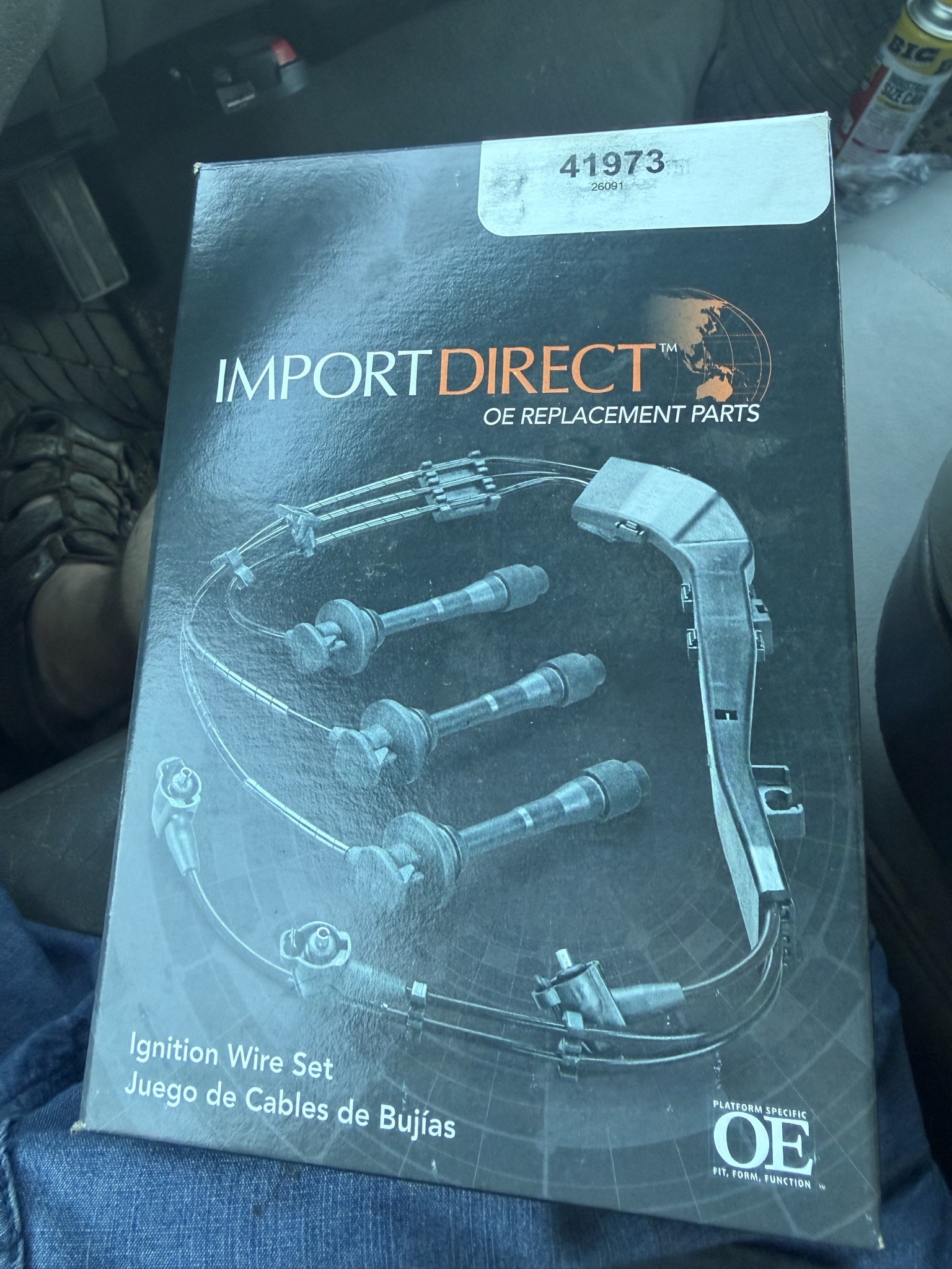
I ended up not using the new distributor cap because it looked really poor quality. The plugs are the same brand, so I don’t trust them. And the rotor was wrong. It was for a different distributor, one that must have a round shank that takes a screw. That is not this distributor. So all those new parts were not put on.
Import Direct is horrible. Never use this, and don’t trust their part numbers.
I did put the new spark plugs in. I’ll probably have to take them back out and clean them off. They had no compression ring, so 1/16 past snug is what I gave them.
The part numbers say why the rotor didn’t fit
The cap box and the distributor body disagree. The box is Import Direct 10-0199, cross referenced on the label to OE 22162-G5711 (→ now SMP JH180). The distributor on the engine is stamped 22100-G5110. Those are two different distributor families, not two spellings of one part. A cap can look close enough to sit on the wrong housing while the rotor, which has to engage the shaft, cannot. That matches what was found, which is a cap that looked wrong and a rotor with the wrong shaft fitting entirely.
Now that the distributor has its own number, ordering gets easier. Search on the distributor’s own numbers rather than on a vehicle application. T4T56371 and 22100-G5110 are both high signal search terms, in a way that “Nissan A15 distributor cap” is not. That is the same technique that found the manuals for this project in the first place.
On the plugs, 1/16 turn past snug is the right call for a gasketless plug. For reference, the factory torque for the plugs on this engine is 15 to 20 N·m (1.5 to 2.0 kg-m, 11 to 14 ft-lb) and the gap is 0.8 to 0.9 mm (0.031 to 0.035 in), both from the engine service manual service data page and both on Specs. Worth gapping them on the bench before they go back in.
Worth confirming the seat type before they go in for good. The plugs recorded off this machine are ACDelco R44T (23 August). A plug that arrives with no gasket is a taper-seat plug, and taper and gasket seats are not interchangeable in the same head. Check which seat the head has and which seat the old plugs used, because getting that wrong changes the reach into the chamber. The engine service manual names the factory plug as an NGK B4ES (p.GI-2), which is a gasket-seat plug, so a gasketless replacement is the odd one out and wants checking before it is torqued down for good.
A broken line at the oil filter
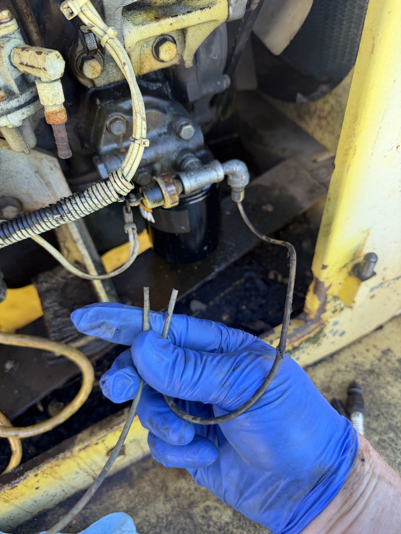
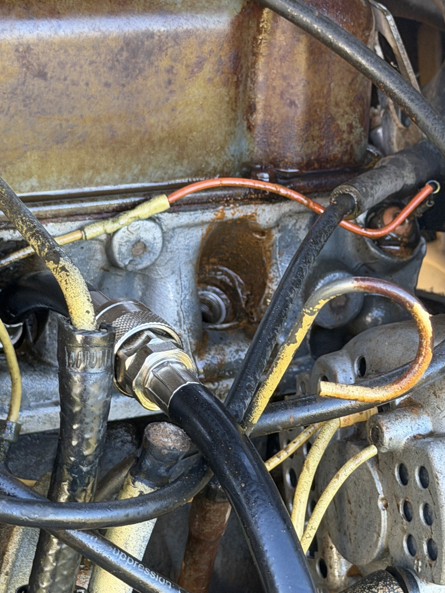
There is also a broken line off the oil centre, off of where the oil filter is. And I’m not sure the fuel pump is working. I will have to test that.
Find out what that line feeds before the engine runs
This is an open oil path, and it has not been identified yet. What the photo shows is a small-bore rigid line at the filter head, broken, with both ends free. If it is fed from the engine’s oil gallery, then the first time the engine makes oil pressure it pumps oil out of that break, and it does it fastest at exactly the moment the bottom end can least afford it, given the bearing journals stood in water (23 August).
It is probably not a sender line for a panel gauge. The parts catalog lists an oil pressure switch, Grove P/N 6872001421, and the operator’s handbook describes it as a normally open switch that closes when pressure falls below 27.5 kPa (4 psi) to sound the engine distress alarm. That is a two-wire alarm switch, not a gauge sender, so it does not want a small-bore oil line running to the panel. No such line appears in the catalog either. The identity is genuinely open rather than merely unlooked-at, and tracing where the other end goes, at the machine, settles it faster than any document will.
Either way it needs blanking or repairing before a start attempt, and that belongs on the pre-start list rather than the tidy-up-later list.
On the fuel pump, the mechanical pump is visible on the block next to the distributor in the photo above. The simplest test needs nothing but the cranking that is already happening. Pull the outlet line into a container and crank. A working mechanical pump delivers in visible spurts, one per camshaft lobe. No spurts means the pump, its pushrod or its diaphragm. That test can be done on the same trip as the compression retest, and it does not need the engine to fire.
Where the oil stands
I checked the oil after cranking it and it still looked clean, so I don’t think there’s a bunch of emulsified oil sitting around in the engine. I will drain it after I get it started.
Clean oil after a cranking pass is a genuinely good sign
This is the first real evidence on the flooded-crankcase question since the sump was drained on 23 August. Cranking stirs the sump. Water left standing in the bottom end would have whipped into the oil and shown as a cloudy brown emulsion on the dipstick. It didn’t. That does not clear the rusted-journal concern, which is about metal surfaces and not about what is floating in the oil, but it does say the flush did its job.
Draining it hot after the first run, as planned, is still the right move. The standing guidance on Specs is that after a flooded crankcase the first fill is a flush and not a service, and it is worth doing more than once.
The plan for next time
To find out
- Whether that switch has to be depressed for the ignition to fire on the lower controls
To check
- The 12 V power coming into the coil
- The schematics, to be prepared to diagnose a no-fire condition
- Whether the fuel pump is working
To buy
- A new coil
- A good cap, rotor and plug wires
Order this
Six lines, about $76. Everything is verified against the OE numbers taken off this machine’s own distributor casting.
| # | Part | Order | Price |
|---|---|---|---|
| 1 | Ignition coil | SMP UC12 | $18.55 |
| 2 | Distributor cap | SMP JH180 | $10.08 |
| 3 | Rotor | Wells 4R1105 | $3.95 |
| 4 | Plug wire set | NGK 8116 | $21.79 |
| 5 | Spark plugs ×4 | NGK 1097 | $8.72 |
| 6 | Ballast resistor | SMP RU13 | $13.33 |
Lines 1 to 4 fit unconditionally. Order, fit, done.
Two rules for lines 5 and 6.
- Plugs. Buy them, do not fit them yet. Check the head seat first, 5/8 in versus 13/16 in on the old plugs and the hole depth. If the head is taper-seat, return these and buy AC Delco R44T, ACDelco P/N 19542401, instead. Nothing else in the order changes either way
- Resistor. Buy it, let the meter decide. Key on, measure the coil + terminal. 6 to 9 V means there is already a drop in the harness and the RU13 stays in its box. Full battery voltage means fit it. Do not fit it blind, because a second drop in series halves the spark
The detail behind every line, including what was ruled out and why, is below and on Specs.
The shopping list, with numbers
Everything below was run down after this visit, off the distributor’s own casting numbers and the factory manual. Sources and caveats are on Specs.
| Part | Order this | Notes |
|---|---|---|
| Spark plugs ×4 | Check the head first. See the warning below | The manual’s plug and the plug in the engine are different plugs. Flat-seat head takes NGK BR4ES, stock no. 1097 (19 mm reach, gasket). B4ES, the plug the manual names, is discontinued and BR4ES is NGK’s own named replacement. Taper-seat head takes AC Delco R44T, ACDelco P/N 19542401 (0.431 in reach, no gasket), which is what has been in it |
| Ignition coil | Standard Motor Products UC12 | Primary 1.3 - 1.5 Ω, oil-filled canister, no internal ballast, external resistor required. Its interchange list carries a block of Nissan 22433- coil numbers |
| Ignition coil, OE route | Nissan 22433-U3110 = HP5-13E10 (→ now SMP UC12) | The factory model. Primary 1.5 - 1.7 Ω, secondary about 9.5 - 11.6 kΩ |
| Ballast resistor | SMP RU13, about $13 | Crosses to OE Nissan 22460-14615 and is 2-terminal, both verified. Not RU13T, which is physically the same part on a 12-month warranty instead of 36, for $3.41 less. Buy it, but the meter decides whether it goes in. No resistor is visible anywhere on this machine, so it is a resistance wire in the harness or genuinely absent |
| Distributor cap | Standard Motor Products JH180 (OE 22162-G5711) | JH180’s own interchange list contains 22162-G5711, this distributor’s OE cap number, and it is a 5-terminal screw-mount cap, matching the one fitted |
| Rotor | Wells 4R1105 (OE 22157-H1000) | 4R1105’s interchange list contains 22157-H1000, this distributor’s OE rotor number, and its mount type is press on, not the round-shank-and-screw type that was rejected on this visit. The genuine Nissan 22157-H1000 is out of production |
| Plug leads | NGK 8116 (NGK part RC-NX71), about $22 | A finished set, no crimping. Catalogued for the 1982 Nissan 310 1.5 L, which is the A15. 7 mm, silicone, suppression core, 90° boots at the cap which is what this one has, four straight plug boots, lifetime warranty. Check the cap-end terminals seat in 22162-G5711 first |
| Plug leads, OE route (→ now NGK 8116) | 22450-G5110 (coil to distributor) plus 22451, 22452, 22453, 22454-G5110 | Five individual Nissan cables against Vanette, A12S / A15S, same G5110 suffix as this distributor. Out of stock at Amayama, so this is the quote-it-to-a-dealer route |
| Cap, rotor and plugs in one box | forkliftpartsworld part 22100, $41 | “Nissan Forklift Tune Up Kit, A15, H20 and Z24 with electronic ignition”. Cap, rotor and four plugs, factory preset. Listed for this exact engine and ignition type. No leads in it |
| Distributor, if it ever needs one | Nissan 22100-G5110 / Mitsubishi T4T56371 | Nissan Vanette KPC22 / KPJC22, engine A15S, 09.1985 to 06.1991. That is the application to search on, not “Grove” or “forklift” |
The plug is not settled, and it is the one thing here that can break something
The manual specifies NGK B4ES. The engine has AC Delco R44T in it. Those are not the same plug.
| NGK B4ES, per the manual | AC Delco R44T, actually fitted | |
|---|---|---|
| Reach | 19 mm (0.750 in) | about 0.431 in |
| Seat | Flat, gasket | Tapered, no gasket |
| Hex | 13/16 in (20.8 mm) | 5/8 in |
| Crosses to | AC R45XL, 47XL | NGK YR5, YR55, BR5FS |
| Buy today | NGK BR4ES / 1097 (B4ES discontinued) | AC R44T / ACDelco 19542401 |
No, the R44Ts cannot hit anything. They are 8 mm too short, not too long. In a flat-seat head the taper cone stops on the counterbore and the electrode sits recessed up inside the threaded hole, so cranking with them in is safe. What they do risk is a carbon-packed thread pocket acting as a pre-ignition hot spot, a marginal cone-on-flat seal that can gall the aluminium, and a plug running hot because it has almost no seat to shed heat through. So crank on them, do not run on them until the head is known.
The interference case is the opposite one. Putting a 19 mm reach plug into a taper-seat head leaves about 0.32 in of plug in the combustion chamber. Full working on Specs.
They do not cross to each other. Either a previous owner has been running badly wrong plugs, or this engine, a Grindstaff reman, does not have a factory head. The head decides, and it is a two-minute check with a light and an old plug. Full procedure on Specs.
Do not order B4ES on the manual’s word. If the head is taper seat, a 0.750 in reach plug sticks about 0.3 in into the chamber and can meet the piston.
This also reopens the torque question. If the head is taper seat, then “no compression ring” is correct and 1/16 turn past snug was the right way to do it. The 11 to 14 ft-lb figure only applies to a gasket-seat head.
On the leads, and a correction
There are plenty of finished sets for this engine, and an earlier version of this page said there were none. That was wrong, and the reason is worth recording. The searches behind it were run against “Datsun” 310 and 210. RockAuto files this car as NISSAN 310, because 1982 sits right on the Datsun-to-Nissan rebadge. Querying the wrong badge returned bulk cable only.
Under Nissan 310, 1.5 L L4, which is the A15, RockAuto lists more than a dozen complete sets. NGK 8116 is the pick, and the alternatives are SMP 27414 (Pro Series, silicone), Walker 9241094 (Direct Fit, suppression core), SMP 7414, Denso 6714008 and Federal Parts 4605 at about $5.33.
The one check before trusting any of them. The 310 is the automotive A15 and its distributor is not this machine’s electronic Vanette unit. The cap families overlap and both take 90° socket boots, but offer the cap-end terminals up to 22162-G5711 (→ now SMP JH180) before routing anything.
And the set already bought is still worth ten minutes. Import Direct 41973 came off an application lookup for this machine and was rejected on brand, not on fit. If its terminals seat and each lead measures under 30,000 Ω, the manual’s own limit, it is serviceable whatever the box says.
Two buying traps found while running these down
- RockAuto does not stock the NGK plug. Searching its part lookup for
B4ESreturns brake pads, and4129returns DENSO 4129, which is a U27FER9, an entirely different plug. Denso and NGK both use four-digit stock numbers and they do not correspond. Do not buy Denso 4129 thinking it is the NGK. And NGK 4129 / B4ES is discontinued anyway, so the number to order is NGK 1097 / BR4ES - Grove has no part number for any of this. The full parts catalog and the MinnPar catalog were both searched and neither carries a coil, plug or lead, because Grove sells the engine as a single assembly (2154800742). All of it is bought on the Nissan / Mitsubishi side
Next steps, in order
Do steps 1 to 3 before ordering anything. They decide which parts to buy.
First, settle the spark plug question at the machine
- Pull one of the plugs that is in it now and look into the hole with a light. A flat machined face at the top of the threads is a gasket seat. A cone partway down is a taper seat
- Thread that old plug back in by hand. If it comes up solid on a cone with the hex still clear of the head, the head is taper seat and R44T belongs there. If it winds in with no distinct seating feel and the hex lands on the head, the head is a gasket seat and the plug is wrong
- Measure the depth, which is unambiguous because the two plugs differ by 8 mm. Drop a thin rod or zip tie down an empty hole until it stops on the piston and mark it level with the head face, then measure the old plug from its seat to the tip of its threads. A hole about 19 mm deep means a flat-seat long-reach head and the R44Ts have been wrong all along. A hole matching the plug’s 11 mm means a taper head and the R44T belongs there. Quicker still, try a socket. R44T takes 5/8 in, B4ES and BR4ES take 13/16 in. Also look for a carbonised ring partway down the hole, which is what a short plug in a long hole leaves behind
Then buy for what the head actually is.
- Flat seat, 0.750 in reach → NGK BR4ES, stock no. 1097, gap 0.031 to 0.035 in, torque 11 to 14 ft-lb. B4ES, the plug the manual names, is discontinued; BR4ES is NGK’s own replacement and is dimensionally identical, differing only by a built-in 5 kΩ resistor, which is fine and arguably better on an electronic distributor. Do not accept BPR4ES, the extra P is a projected tip
- Taper seat, 0.431 in reach → AC Delco R44T, ACDelco P/N 19542401, or NGK YR5, torque 1/16 turn past snug, which is what was already done on this visit
Then the ballast resistor, before the new coil goes anywhere near it
No ballast resistor is visible anywhere on this machine. The coil sits in a band clamp on a bare bracket with two spade wires and nothing else. So it is a resistance wire in the harness, mounted somewhere not photographed, or missing. Find out before fitting a 1.5 Ω coil, because running one of those on an undropped 12 V feed cooks it, and the coil that came off reads 4 Ω primary against a 1.5 Ω spec, which is what a cooked coil looks like.
- Check the platform emergency stop is pulled out, and the ground ignition switch on
- Key ON, not cranking. Measure voltage at the coil + terminal.
- 6 to 9 V means a resistor or resistance wire is in circuit and working. Nothing to buy
- Full battery voltage means nothing is dropping it, and a 1.6 Ω resistor has to go in before the new coil runs
- Measure the same terminal while cranking. It should rise to near full battery voltage. That is the cranking bypass the engine manual describes (p.EL-15). If it does not rise, the bypass is a fault in its own right
- To locate it, disconnect the coil + wire and measure from that wire back toward the ignition switch. Around 1.6 Ω means it is in that path, as a block or a resistance wire. Near 0 Ω means it is not there at all
- If one is needed, fit SMP RU13. It crosses to OE Nissan 22460-14615 and is 2-terminal, both verified. Not RU13T, the value-line version of the same part with a 12-month warranty instead of 36. Not RU10, which is a GM part with no Nissan cross-reference at all. Meter whatever arrives, 1.5 to 1.8 Ω is fine
Then the rest of the ignition
- Fit the new coil, cap, rotor and leads
- Confirm the No. 1 cap tower is still the one facing the rear of the vehicle and paint-mark it
- Gap and fit the correct plugs from step 3
Everything here is the gasoline setup, not the LP one
This machine is factory dual-fuel, and none of the ignition figures above account for it.
The Nissan engine manual is gasoline-only. Its Engine Fuel section is fuel pump, carburettor and governor, its maintenance schedule has no LP column, and a loose search across all 91 pages of a fresh 250 dpi OCR finds nothing. The other manuals do carry dual-fuel material, though, and an earlier version of this page wrongly said they did not.
- The Grove handbook has the FUEL SELECT switch (GAS / neutral / LP) and both changeover procedures at p.4-4, plus the dual-fuel starting procedure at p.4-3
- The IMPCO catalog has a Standard LPG Fuel System Engine Maintenance Schedule at p.7 with its own ignition service intervals, and the HD-5 / HD-10 fuel specification
- The parts catalog carries a dual-fuel-only view, the LP vacuum circuit and the DANGER LP GAS decal, 7376007521
- The wiring diagram carries LP START, LP-VACUUM and LP-FUEL relay K34
What none of them give is LP ignition specs for the A15, meaning heat range, gap and timing.
For the plan as it stands that is fine, because the first start is on gasoline from a separate can with the LP side still disconnected. BR4ES at 0.031 to 0.035 in and 10° BTDC are the right numbers for that.
Do not flip the fuel selector to LP and assume the ignition suits it. General LPG practice, which is not sourced from anything in this project, runs a colder plug, often a smaller gap, and usually more advance. Worth knowing that heat range 4 is already the hot end even for gasoline — third-party data on the automotive A15 lists BPR5ES as standard with BPR4ES as the hot option. On LP that is the wrong direction to be starting from. Full note on Specs.
Then the mechanical work
- Retest compression wet and dry, watching the gauge return to zero between cylinders, writing every number down against its cylinder
- Test the fuel pump by cranking its outlet into a container
- Identify the broken line at the oil filter head, then blank or repair it
- Re-torque the crank bolt to 108 to 145 ft-lb and re-attach the radiator, both carried over from the 07 September plan
- Then, and only then, try for a start
Don’t bother with the Grove parts catalog for any of this
It carries no spark plug and no ignition coil, and that is now closed three ways rather than being an unsearched gap.
- Full-text search of all 400 pages returns zero hits for “SPARK”
- The Alphabetical Index runs SOLENOID, SOLENOID ASSY, SPACER, SPADE, SPINDLE, SPOOL, SPRING. SPARK would sort between SPADE and SPINDLE and there is no gap, so it was never in there. The only COIL entries are hydraulic manifold coils
- Grove’s own Belt and Filter Maintenance List has exactly four line items and none is an ignition part, or even the engine oil filter
Grove buys the engine in as a single assembly, 2154800742, and the “POWER UNIT INSTALLATION - NISSAN A-15 (GAS)” section (catalog pp.137-143) is brackets and cap screws. Every ignition and tune-up part comes from the Nissan / Mitsubishi side.
What the catalog is good for is the four items it does list, which are worth having on the same order. Fuel filter 7437000104, air cleaner element 9304100091, hydraulic oil-return element 9304100081, hydraulic pressure element 9437100642.
Where this leaves it
| Was | Now |
|---|---|
| Compression unknown. Bore and valve condition unknown after a flooded engine | Compression on all four. Best readings 185 and 180 psi, at the 181 psi factory standard, plus a 120, a 120 and a 90. Three readings near 250 psi are above what the engine can physically make and point at liquid still in the bore |
| Turns by hand only | Turns on the starter, in long pulls, clearing debris and penetrant out of the bores |
| No-spark condition unexplained | Coil secondary reads open circuit, measured twice on different terminals. Sufficient on its own to explain no spark |
| No distributor number ever read off the machine | T4T56371 / 22100-G5110, stamped on the body. A T4T number, which is not either points unit in the engine manual |
| “Switch in basket must be up”, switch unidentified since 22 August | Reads as “kill switch in basket must be up”, which matches the platform emergency stop in the operator’s handbook. Not yet verified on the machine |
| Whether the lower-panel selector gates the ignition, unknown | Reads as control power only, not ignition, from the machine’s placard and the handbook. Still worth the thirty-second meter check, since the cranks-on-the-key test could not discriminate with a dead coil |
| Crankcase water status after the flush, unknown | Oil still looked clean after a cranking pass |
| Nothing known to be broken at the oil filter head | A small-bore line there is broken, both ends free, function not yet identified |
Next out.
- Check the coil feed, and check the platform emergency stop is pulled out
- Fit a new external-resistor coil, with a cap, rotor and leads that actually match 22100-G5110
- Retest compression wet and dry, watching the gauge return to zero between cylinders, with every number written down against its cylinder
- Test the fuel pump by cranking it into a container
- Sort the broken line at the filter head before asking the engine to make oil pressure
Back to My Story · 07 Sep 2026 · Specs · Firing Order · Checklists · Research