22 Aug 2026 - Second Look
22 Aug 2026 - Second Look
Second trip out to the machine, cap off and camera out.
Three things came out of this one. Two of them I’d had wrong, and the third is now the biggest question hanging over the machine.
Cylinder 2 was full of water
All the other cylinders were clean, but number 2 was full of rainwater. I blew it out with compressed air and soaked all four cylinders down with PB Blaster.
I couldn’t get the engine to turn at that point, so I moved the radiator out of the way a little to get better access to it. One of the lower radiator mounts broke free while I was doing that — it had rusted through. I think I’ll epoxy it back together once it’s running.
Findings — the water is settled; the seizure is not
Source of the water: rain, through the open plug hole. The plugs were out when the machine was bought and the holes have stood open in the weather since. Not a head gasket, not a cracked casting.
The water is not why it would not turn. With the plug holes open, water in a bore cannot hydrolock anything — the piston pushes it straight back out of the hole. The seizure is a separate, rust-driven problem.
What the water does mean: No. 2 has stood wet, so surface rust and rings rusted to the bore are likely there specifically. That makes No. 2 the most probable single point of seizure, and it is what the PB Blaster soak is aimed at.
Method for freeing it is in the startup procedure §1a. (This finding was overtaken the following day — a gallon of water out of the crankcase moved rusted bearing journals up alongside ring rust as the likely cause. See 23 Aug.)
On the radiator mount: epoxy will not hold a radiator mount on a machine that vibrates under load, and bonded repairs on rusted steel fail in exactly this service. A welded replacement tab, or a fabricated bracket through-bolted with a rubber isolator, is the repair that lasts. Epoxy is fine as a temporary hold while measuring for the real fix.
Ignition
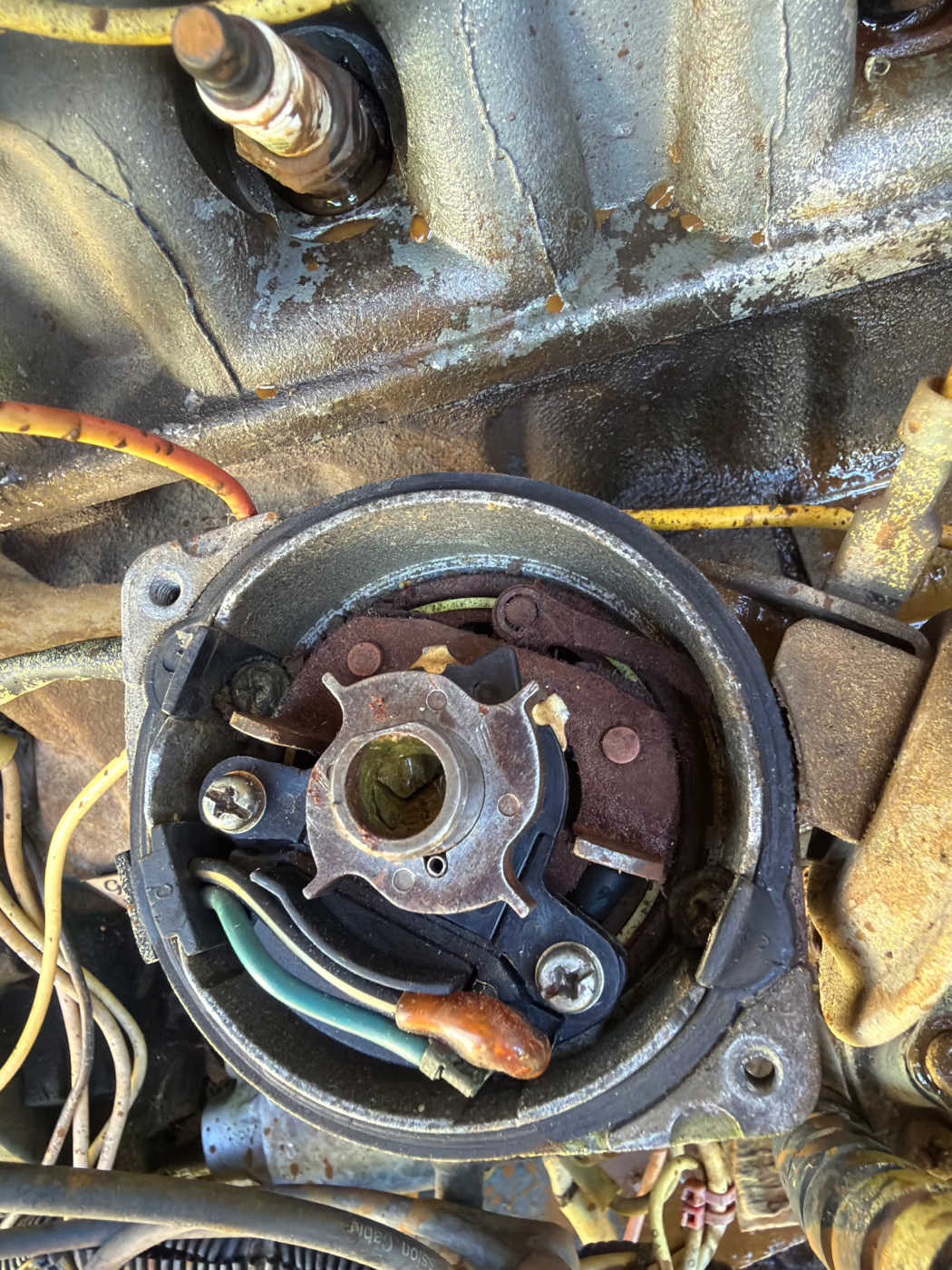
The distributor is electronic. There are no points in it. The vacuum actuator mechanicals need a little silicone spray to free them up.
Findings — this corrects the spec sheet
Visible in the photo: a four-lobe reluctor star on the shaft with a crescent magnetic pickup beside it, and the pickup’s blue/green pair running to the harness. No contact set, no condenser, no breaker plate.
The Nissan engine service manual documents a breaker-point distributor — Mitsubishi T3T03581 for the A15 — and its point gap (0.45–0.55 mm) and dwell (49°–55°) figures follow from that unit. Neither applies to this engine. Both are now flagged as not applicable on Specs.
Grove’s own paperwork had this right the whole time: the engine harness drawing in the parts catalog (catalog p.154, harness assembly 6512002038) labels a tap point “TP R — ELECTRONIC DISTRIBUTOR & ANTI-DIESEL SOLENOID.” That label had been found and flagged as needing physical confirmation. It was correct.
What does not change: firing order 1-3-4-2, rotor turning counter-clockwise, No. 1 cylinder at the front. Those are properties of the engine, not of the trigger mechanism, so the firing order and plug wire routing procedure applies unchanged.
One caution on the silicone spray. The factory distributor exploded view (p.EL-16) marks specific high-temperature grease points inside the housing: governor weights and springs, the shaft, the advance plate and its pivot, and the cam. Those want grease, not spray lubricant — spray will thin and wash out what grease remains. Silicone on the external vacuum-diaphragm linkage is fine. Keep it off the reluctor and the magnetic pickup.
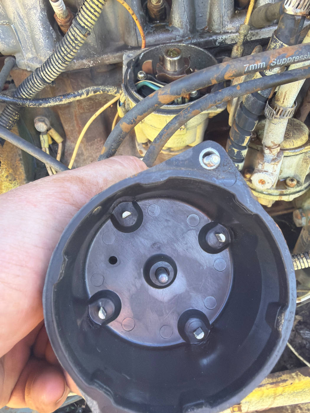
The distributor cap looks good.
Findings — the cap is serviceable, and it is keyed
The inside face is clean: no carbon tracking, no cracks, and the centre carbon button is intact — the factory wear limit is more than 3 mm (0.12 in) of button remaining, and there is plenty left. Four electrodes evenly spaced at 90°.
The detail that matters for rewiring is the locating hole off to one side: the cap is keyed and only fits the housing one way. Once the No. 1 tower is identified, that identification stays valid every time the cap comes off and goes back on.
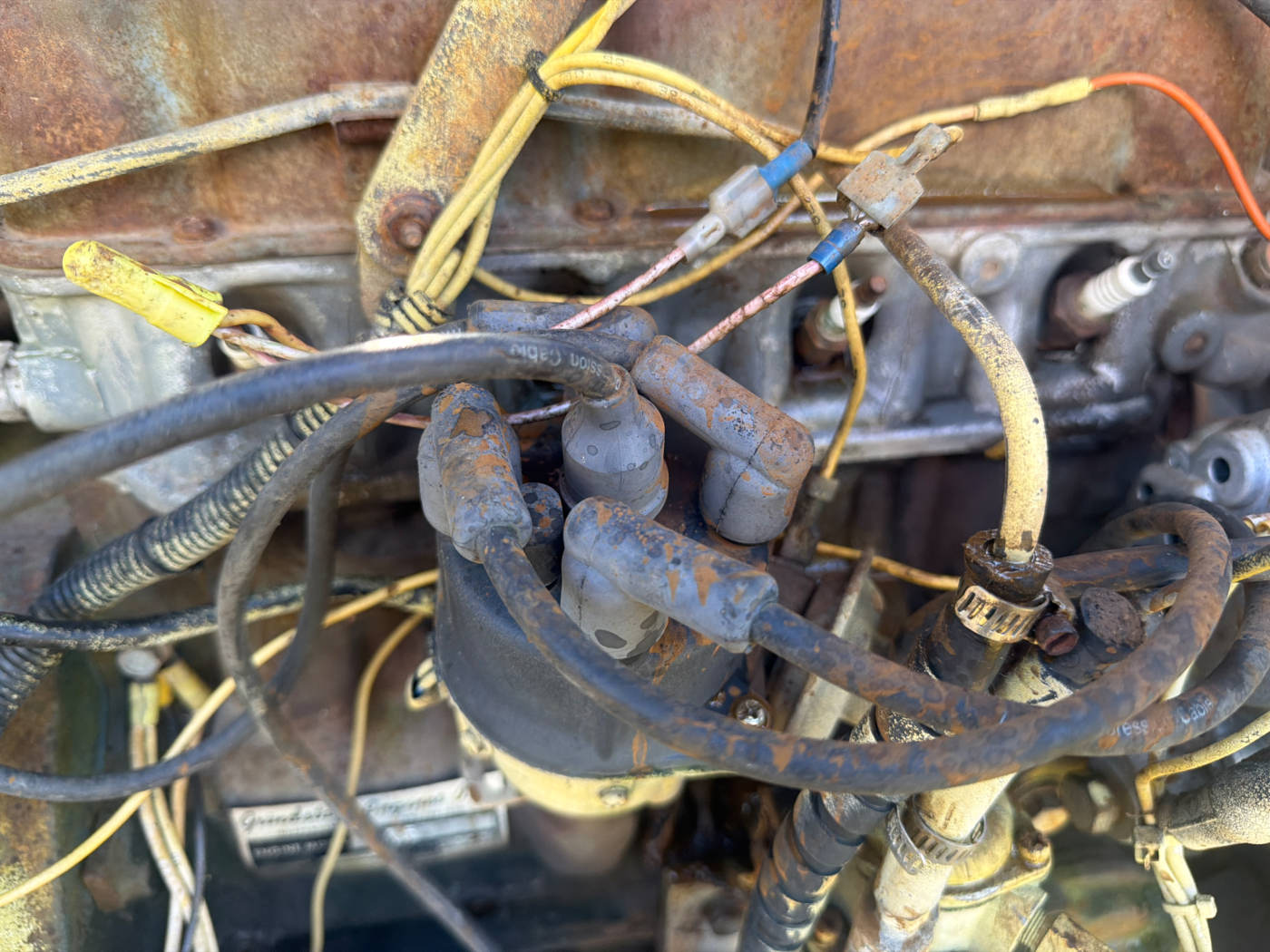
I took this one before I pulled anything apart, so it’s my record of how the plugs, wires, cap and rotor were sitting when I got the machine.
I still need to know the firing order.
Findings — the as-found routing, and why not to trust it
This photo was taken before anything was disturbed, so it is the only record of how the plug wires were routed when the machine was acquired. Worth keeping as a reference — but not worth relying on. There is no way to know whether the last person to work on it had it right, and individual leads cannot be traced reliably in a photograph.
Establish No. 1 from the engine instead: No. 1 piston at TDC on the compression stroke, note which tower the rotor points at, then walk the cap counter-clockwise 1 → 3 → 4 → 2. Full procedure with the diagram: Firing Order & Plug Wires.
The existing leads are printed “7mm Suppression” — generic aftermarket wire, not an OEM set. Updated 09 Sep 2026: the set to buy is NGK 8116 (RC-NX71).
Any quality 7 mm four-cylinder set with the correct boot styles will replace them; there is no need to chase a Nissan part number for the wire.
“Points and rotor” comes off the shopping list. It is plugs, wires and a rotor.
The disconnected coil
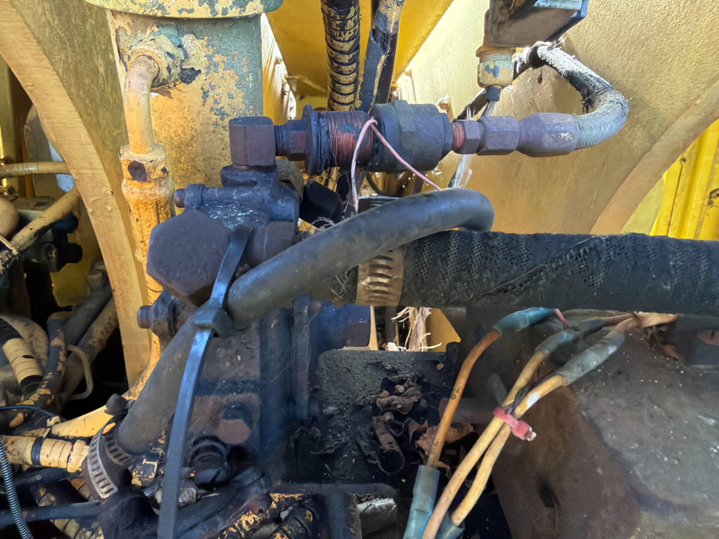
The coil I thought was for the hydraulics is actually for the propane regulator.
Findings — this corrects the research, and confirms the dual-fuel option
Research §4.2 had this narrowed to a shortlist of individual solenoid coils on Grove’s hydraulic manifold (P/N 7926003166), reasoning from its position at the hydraulic filter cluster with the hydraulic line running past it. That reasoning was sound and the conclusion was wrong. The coil is on the LP line — it is the propane regulator / lock-off.
Two pieces of evidence had pointed this way and were under-weighted:
- The sales brochure lists “Nissan A-15 dual/fuel engine” as a factory option on the MZ48B/MZ66B.
- The same Grove engine harness sheet that named the electronic distributor also carries an LP vacuum switch. An LP vacuum switch is not wired onto a gasoline-only machine.
Conclusion: this machine was built with the factory dual-fuel option. That has consequences beyond identifying one coil — the FUEL SELECT switch at the ground controls is functional, the LP side is a real fuel system that must be treated as one, and it cannot be left permanently half-connected. Leaving it disconnected for a gasoline-only first start remains correct.
Fuel, filters and battery
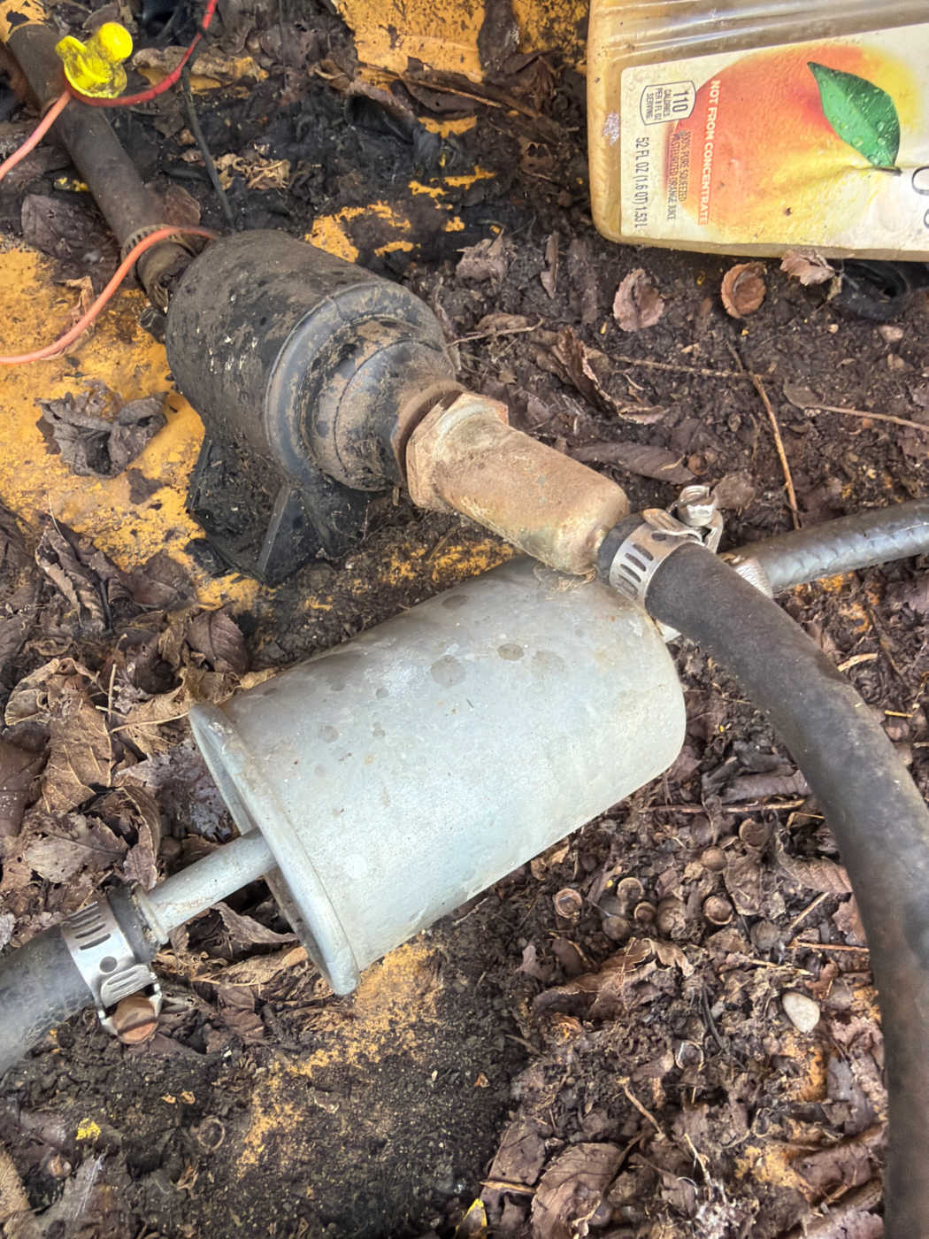
Running list of what it needs: oil change, fuel filters, oil, a battery, big sockets to turn the crank, and an inline fuel filter.
Findings
The fuel line carries an inline filter and a canister spliced in with hose clamps — an aftermarket arrangement, not Grove’s. Grove’s own fuel filter number for this machine is 7437000104 (parts catalog p.139); the full consumables list with provenance is on Specs.
On “big sockets to turn crank”: the crank pulley bolt is torqued to 108–145 ft-lb, so barring the engine over by hand calls for a proper socket and bar rather than a ratchet.
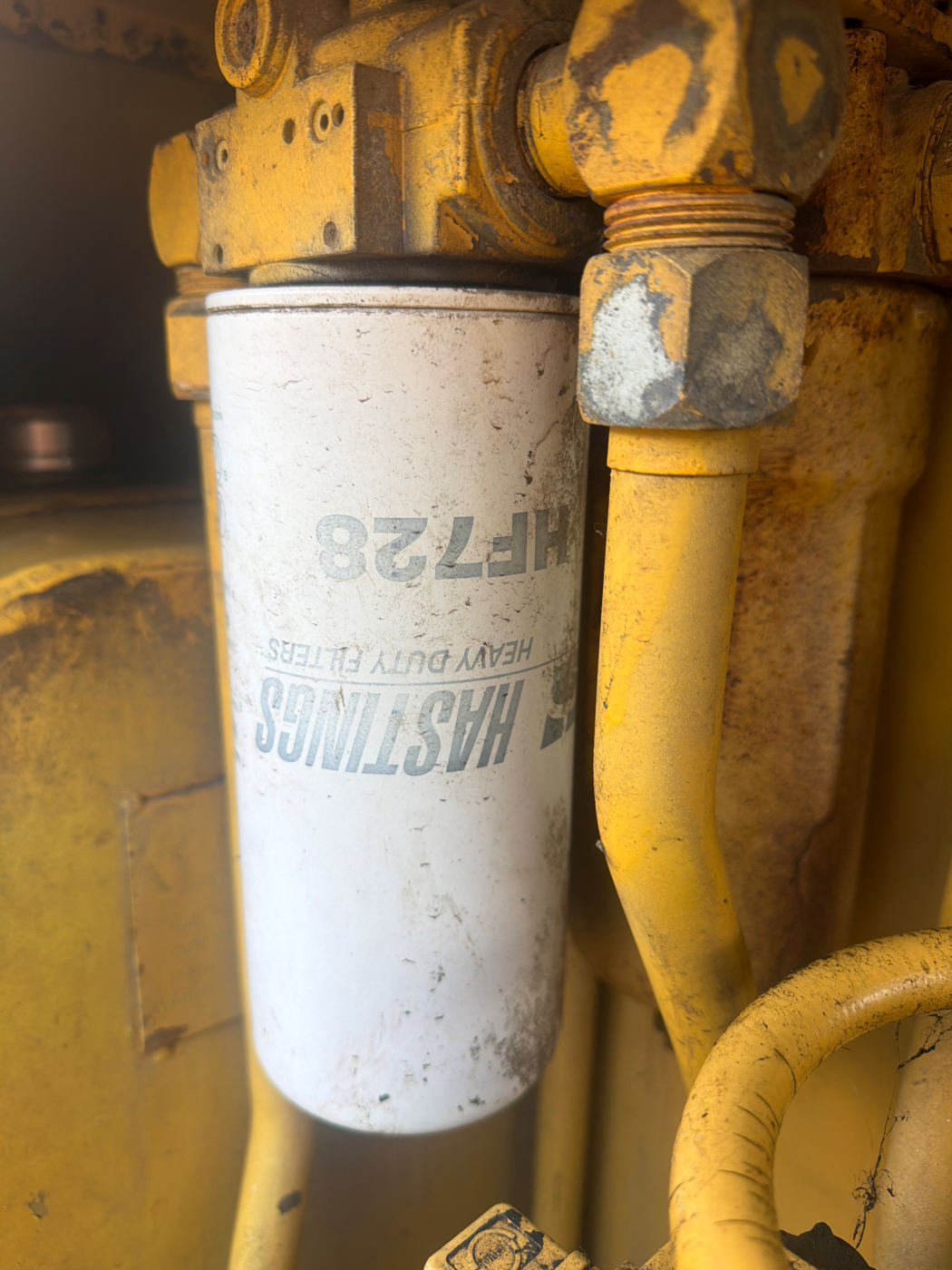
Hydraulic oil filter goes on the list too.
Findings — the most immediately usable part number from this trip
The hydraulic filter physically fitted is a Hastings HF728 spin-on. That can be bought over a counter with no cross-referencing.
Worth reconciling: Grove’s catalog describes hydraulic filtration in terms of cartridge elements in housings (pressure element 9437100642, oil-return element 9304100081), and what is on the machine is a spin-on. Either a previous owner converted it, or this build shipped with spin-ons. Either way HF728 matches the hardware actually bolted to the machine, which is what governs.
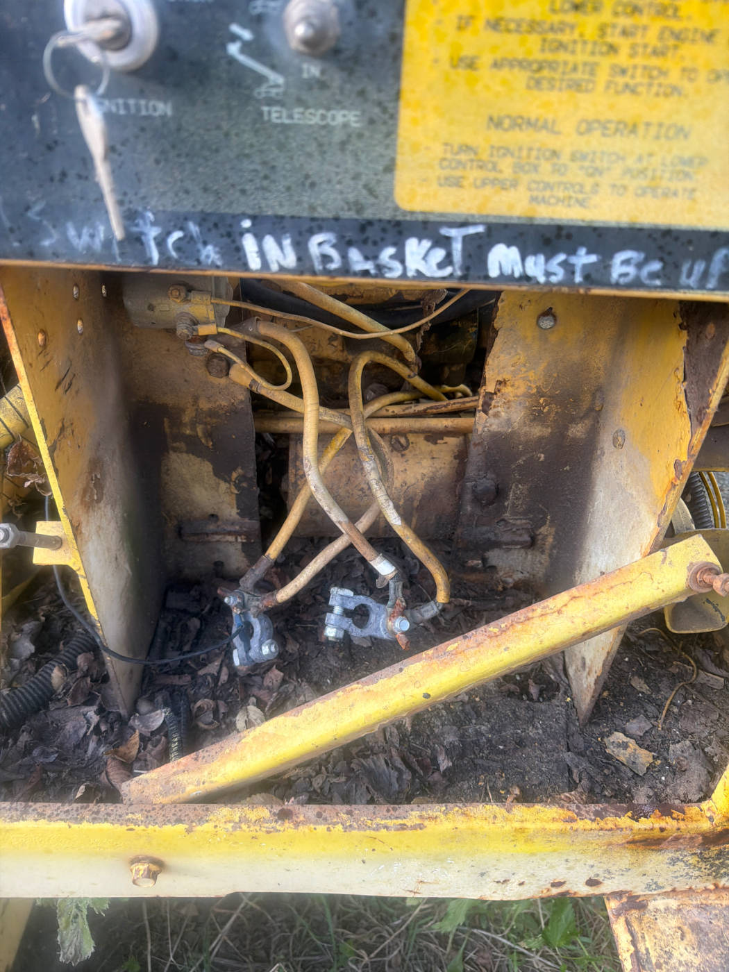
Spark plugs, and I need to bring an air compressor. The battery is missing entirely — there’s nothing in the tray but the cables.
I went to the auto parts store and they found the plugs and the engine oil filter by looking up the A15 motor.
Findings — battery specification
No battery fitted; the cables are lying loose in the tray. The factory sales brochure specifies a 12-volt DC negative-ground battery, 625 CCA @ 0 °F (−17 °C), and Grove’s battery installation (assembly 6978003592, catalog p.227) is a single 12 V battery — Grove P/N 7064000034 — on a plywood base with an angle hold-down. No BCI group size is published in any document held here, which is why measuring the box is the right next step. Full detail on Specs.
The counter lookup closes the engine oil filter gap that the manuals could not — worth recording the number that was supplied so it does not have to be looked up again.
Also visible in this shot, written on the frame by a previous owner:
“Switch in basket must be up”
Which switch that refers to is not yet established, and it should be identified before it is relied on.
Resolved 09 Sep 2026. A photo from that visit catches an adjoining stretch of the same marker line and the missing word. It reads “Kill switch in … basket must be up”, which matches the platform EMERGENCY STOP described in the operator’s handbook.
Control panel
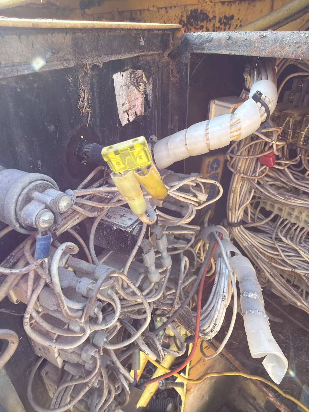
Not an issue, just noting it — somebody replaced the two glass fuses in the control panel with ATO fuses.
Findings
What’s actually in there: the two original glass fuses have been replaced with ATO (blade) fuses — an inline conversion by a previous owner, not a jumper and not a defeated circuit. The protection is still present.
The one thing worth checking is rating. An ATO swap is only as good as the amperage somebody chose, and the fuse bodies in the photo read as standard ATO colours rather than anything matched to a Grove spec. Confirm the ATO ratings against what the original glass fuses were, and against the control-circuit ratings on the schematic (Electrical & Hydraulic Schematics). An over-rated fuse on a control circuit is the failure mode to rule out here — not the conversion itself.
Tires
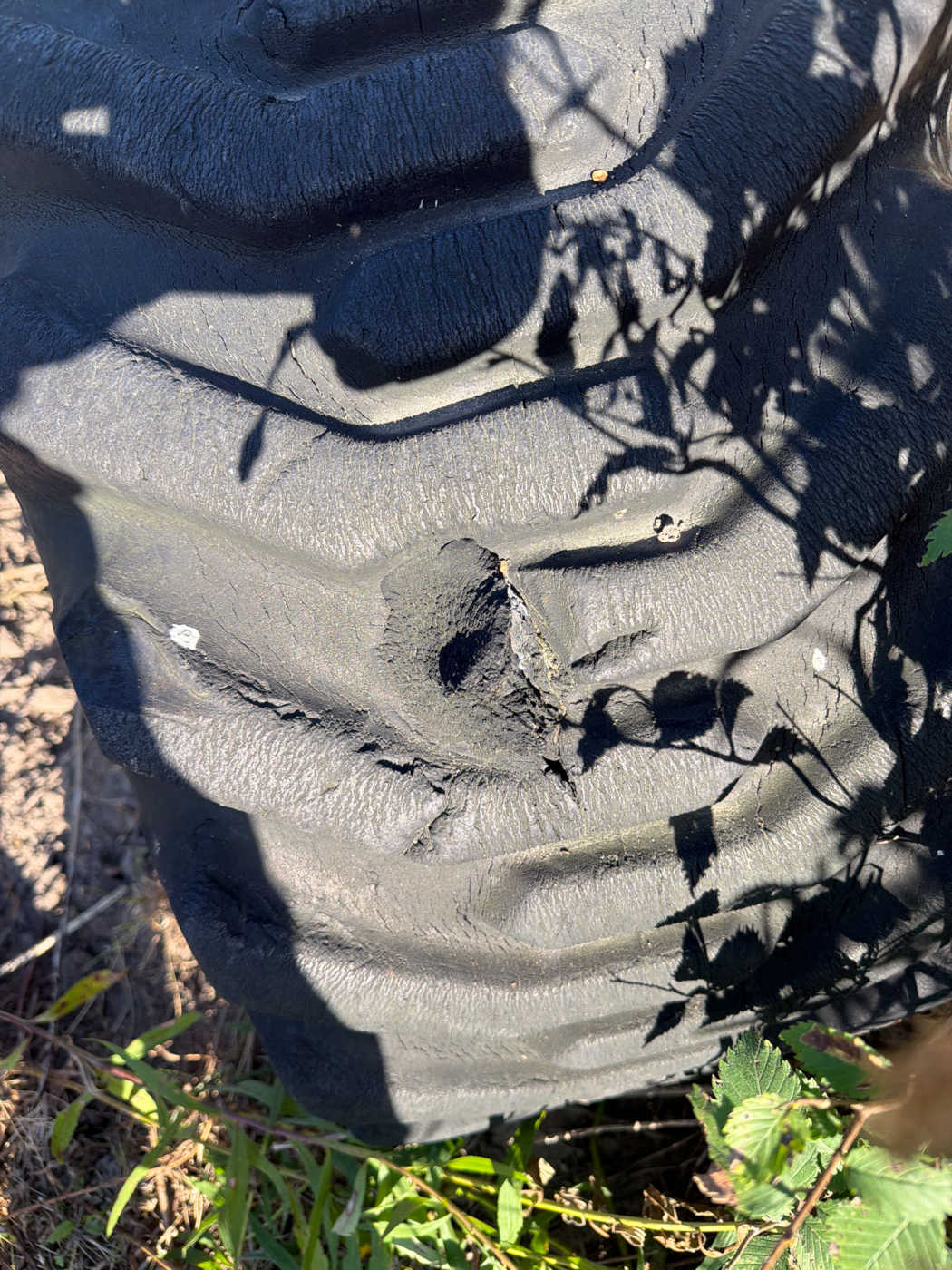
The tires are in the worst shape of anything on this machine. I initially thought the front right had a hole in it.
Findings — a stability issue, not a maintenance item
The front right has a substantial chunk gouged out of the tread and shoulder.
The operator’s handbook is explicit about this: substituting or replacing foam-filled tires with pneumatic ones alters machine stability and can cause serious injury or death, and a foam-filled tire/wheel assembly is bonded together — if either the tire or the wheel is damaged or worn, the complete assembly must be replaced.
Specs records this machine’s tires as 15x19.5-12PR, air-filled, from the sales brochure. Confirm by hand whether these particular tires are air or foam before ordering anything, because the two paths differ completely. Nothing goes in the air until the tires are resolved.
Next time out
Wiggle the crank and try to get the engine free, silicone the distributor linkage inside the housing, measure the battery box, drain the fuel and the oil, take pictures and report back.
That’s the next day — and the engine turned out to be a lot wetter than one cylinder.
Summary of what changed in the documentation
| Was documented as | Corrected to |
|---|---|
| Points-type distributor; point gap 0.45–0.55 mm, dwell 49°–55° | Electronic distributor, no points. Those two figures do not apply — Specs |
| Mystery coil = one of the solenoid coils on hydraulic manifold 7926003166 | Propane regulator on the LP line. Machine carries the factory dual-fuel option — Research §4.2 |
| Firing order recorded as a bare sequence from a forum post | Confirmed from the factory table, with a full routing procedure — Firing Order & Plug Wires |
| No reason recorded for the engine not turning | Engine is seized. No. 2 was full of rainwater from the open plug hole, but that isn’t the cause — with the holes open nothing can hydrolock. It’s rust |
Open, roughly in the order they matter:
- Getting the engine to turn. Soak over days rather than one hit, and rock it rather than heaving on it. (Superseded the next day — see 23 Aug, where a gallon of water came out of the crankcase.)
- Whether the tires are air or foam filled, and what the front right needs.
- A durable repair for the lower radiator mount.
- Which switch the basket note refers to, and whether the ATO fuses in the control panel are the correct rating.
- The chewed limit switch harness — trace and replace that section, not splice it.