Firing Order & Plug Wires
Firing Order and Plug Wire Routing — Nissan A15
Standalone answer to “all the plug wires are off, what goes where.” Everything below is from the Nissan factory engine service manual unless flagged otherwise. See Specs for the rest of the ignition data.
This was not previously documented anywhere in this project — Specs and
Research carried the bare sequence 1-3-4-2 and nothing about which tower is which.
That gap is what this page closes.
The map at a glance
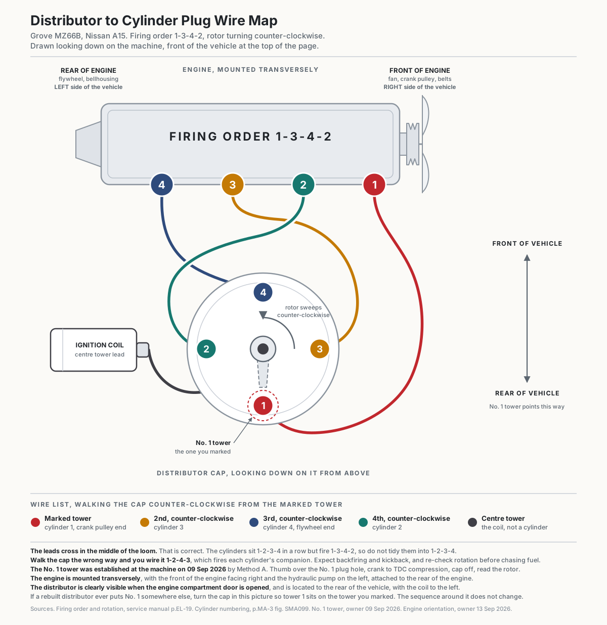
Everything in that drawing is worked through below. The rotor sweeps counter-clockwise and the leads walk 1-3-4-2 around the cap onto cylinders that sit 1-2-3-4 from the front of the engine to the rear. No. 1 is the tower facing the rear of the vehicle.
The three facts you need
| Fact | Value | Source |
|---|---|---|
| Firing order | 1-3-4-2 | Service manual p.EL-19 (PDF p.90), Service Data and Specifications → DISTRIBUTOR. The A15 column of the factory table |
| Rotor rotation | Counter-clockwise (viewed from above, cap off) | Same table — “Rotating direction: Counterclockwise,” spanning both the A12 and A15 columns |
| Cylinder numbering | No. 1 is at the FRONT — the crank pulley / fan / drive belt end. No. 4 is at the flywheel end. | Service manual p.MA-3 (PDF p.10), Fig. SMA099 — the valve-adjustment figure carries a “Front” arrow, and the No. 1 cylinder step adjusts the two front-most valves |
Note the firing order used to be sourced here from a Datsun forum post. It is now confirmed against the actual factory spec table, so treat it as hard fact.
Cylinder layout
        FRONT of engine                              REAR of engine
   (crank pulley, fan, belts)                    (flywheel, bellhousing)
              │                                            │
              ▼                                            ▼
          ┌───────┬───────┬───────┬───────┐
          │  CYL  │  CYL  │  CYL  │  CYL  │
          │   1   │   2   │   3   │   4   │
          └───────┴───────┴───────┴───────┘
“Front” here means the front of the engine, not the front of the machine — the end the crank pulley and drive belts are on. Don’t infer it from how the engine sits in the chassis.
Step 1 — find which cap tower is No. 1
The cap towers are evenly spaced and nothing on the cap identifies them, so you have to establish No. 1 from the engine itself. There are two independent ways, and they should agree — do both, because if they disagree you have a mis-installed distributor, not a wiring question.
Method A — rotor at No. 1 TDC compression (the one to trust):
- Pull all four spark plugs. Cranking is far easier with them out, and you need No. 1’s hole open.
- Put a thumb over the No. 1 (front-most) plug hole.
- Turn the crank in its normal running direction — clockwise as you look at the crank pulley from
the front of the engine — until you feel compression pushing your thumb off the hole. That tells
you No. 1 is on its compression stroke, not its exhaust stroke. This distinction is the whole
point: the crank turns twice per cycle, so No. 1 comes up to TDC twice, and only one of those is
the firing position.
- The crank pulley bolt is torqued to 108–145 ft-lb, so it will not back off while you lever on it. If you would rather bump the starter, do it in short taps and keep hands clear.
- Keep going in the same direction until the timing mark on the crank pulley lines up with TDC (0°) on the timing indicator.
- Pull the distributor cap. Whichever tower the rotor tip is now pointing at is cylinder No. 1. Mark it with a paint pen or a scratch before you put the cap back on.
Method B — the cast “No. 1 mark” on the distributor:
The factory manual (p.EM-16, PDF p.38, Fig. EM-78 “Correct Position of Rotor”) shows a “No. 1 mark” cast into the distributor housing. With No. 1 at TDC compression, the rotor tip should be sitting on that mark. Use this to cross-check Method A. If the rotor is 180° from the mark, you are on the exhaust stroke — turn the crank one more full revolution and check again.
Step 2 — walk the cap counter-clockwise
Once you know the No. 1 tower, everything else falls out of the rotation direction. The rotor turns counter-clockwise, so the next cylinder in the firing order is the next tower counter-clockwise from the one before it.
        DISTRIBUTOR CAP — looking DOWN on it from above, cap removed
        Rotate this picture so that "CYL 1" sits on the tower you
        marked in Step 1. The cap's clocking on the engine varies;
        the sequence around it does not.

                              CYL 1
                                ●
                                │
                                │
              CYL 3   ●─────────⊕─────────●   CYL 2
                                │      (centre tower
                                │       = coil wire)
                                ●
                              CYL 4

                    ↺  rotor sweeps counter-clockwise
                       1 → 3 → 4 → 2 → back to 1
Written out as a wire list, starting from the tower you marked:
| Tower, counter-clockwise from No. 1 | Goes to |
|---|---|
| 1st (the marked one) | Cylinder 1 — front-most plug |
| 2nd | Cylinder 3 |
| 3rd | Cylinder 4 — rear-most plug, flywheel end |
| 4th | Cylinder 2 |
| Centre tower | Coil high-tension lead — not a cylinder |
Because the order is 1-3-4-2 and the cylinders are physically 1-2-3-4 in a row, the wires cross over each other in the middle of the loom. That is correct and expected — don’t “tidy” it into 1-2-3-4.
Getting the direction wrong: what it looks like
If you walk the cap clockwise instead of counter-clockwise you will wire it 1-2-4-3, which fires each cylinder’s companion instead of the cylinder itself. The engine will not run. Expect loud backfiring through the carburettor and/or the exhaust, and possibly a kickback while cranking. If you get that, don’t chase fuel or timing — re-check the rotation direction first.
While the plugs are out anyway
| Item | Spec |
|---|---|
| Plug gap | 0.8–0.9 mm (0.031–0.035 in). Gap to 0.032–0.035 in. Which plug is still open, the factory NGK B4ES → now BR4ES, stock 1097 is a 19 mm gasket-seat plug while the AC Delco R44T in the engine is a 0.431 in taper. See SPECS.md |
| Plug torque | 15–20 N·m (11–14 ft-lb) |
| Plug wire resistance | Less than 30,000 Ω per lead. Worth checking all four with a meter before you reinstall — this machine sat, and cracked or high-resistance leads are a classic sitting failure |
| Ignition timing (after it runs) | 10° BTDC at idle. A12 is 12° — this is an A15, use 10° (p.MA-7) |
Full ignition spec table is in Specs → “Ignition.”
Also worth doing while the cap is off, as of 09 Sep 2026. The ignition coil ohmed out with an open secondary and is being replaced. Buy an external-resistor coil to match what came off, and find the circuit’s dropping resistor and its cranking bypass while the meter is out. Details on Specs under “Note on the ignition coil.”
Which distributor is it
Read off the distributor body casting on 09 Sep 2026. Two numbers are stamped into the aluminium.
| Number | Whose |
|---|---|
| T4T56371 | Mitsubishi Electric unit number |
| 22100-G5110 | Nissan part number |
The second character of the Nissan suffix is stamped on a rough casting. It reads as a G, but take a light to it before ordering anything against it.
Order cap, rotor and leads against these numbers, not against a vehicle application. They are high-signal search terms in a way that “Nissan A15 distributor cap” is not. A cap bought on an application lookup in September 2026 (Import Direct 10-0199, boxed as OE 22162-G5711 (→ now SMP JH180)) turned out to be poor enough quality not to fit, though its OE cross-reference was actually correct. The separately bought rotor was the real mismatch, a round shank taking a screw, which this distributor does not use. See 09 Sep 2026.
Points or electronic, settled. It is electronic
Three independent sources agree, so treat this as fact rather than an open question.
- Physical inspection, 22 Aug 2026. Cap off, no contact set and no condenser inside
- Grove’s own engine harness drawing (parts catalog, catalog pp.152-154 / PDF p.169, harness assembly 6512002038) labels a tap point for an electronic distributor alongside the anti-diesel solenoid. That label is read off the drawing image and does not appear in the extracted text, so it is not quotable as a text hit
- The casting number, 09 Sep 2026. The Nissan service manual documents this engine’s distributor as Mitsubishi T3T03581, a breaker-point unit, and publishes point gap and dwell figures for it on the service data page (p.EL-19, PDF p.90). The T3T03671 alongside it is the A12 column of the same table, not a second option for the A15. The unit actually fitted is a T4T number, a different and later family
What follows from it. The point gap and dwell specs in the Nissan manual do not apply to this engine and are struck through on Specs. There is no condenser inside, and none is needed. A condenser exists to stop mechanical points burning themselves out, and there are no points here. Some electronic units carry a small external noise-suppression capacitor on the housing, which is a different part and is not required for the engine to run. None of this changes the firing order, rotation direction or cylinder numbering above, which are identical either way.
Which tower is No. 1 on this engine, established 09 Sep 2026
Method A was done on this machine and the answer is recorded. Thumb over the No. 1 plug hole, crank to compression, carry on to TDC, cap off, read the rotor.
No. 1 is the tower facing the rear of the vehicle. The leads then walk counterclockwise 1-3-4-2 from there, per Step 2 above.
How the engine sits in the machine
Established 2026-09-13.
- The engine is mounted transversely
- The front of the engine faces right
- The hydraulic pump is on the left, attached to the rear of the engine
- The distributor is clearly visible when the engine compartment door is opened, and is located to the rear of the vehicle
- The coil is to the left
- The drawing at the top of this page is clocked to match, looking down from above with the front of the vehicle at the top of the page
Method B, the cast “No. 1 mark” on the distributor housing, is still worth a glance as a cross-check whenever the cap is next off.